 |
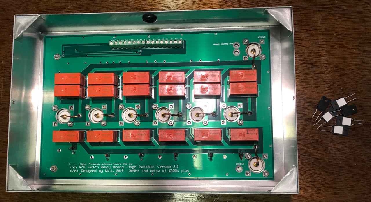
| My KK1L board, showing the old resistors on the board, and the new ones on the desk. |
I originally used 50 ohm, 1/2 watt resistors I had on hand. Clearly they were not up to the task. On the ports for the shunt-fed tower, and the 80/40/20m trap dipole, these resistors were completely open. Both showed signs of overheating.
Most likely, these resistors succumbed to dissipating too much couple RF energy. I needed bigger ones. KK1L had 50 ohm, 50 watt resistors in his Mouser parts list, so that's what I ordered. These sorts of things come in handy, so I bought ten. Due to supply chain issues, they were back-ordered for months. But they finally arrived.
Replacing these parts is a pain. First, I had to remove the KK1L box from the SPG panel. Next, I had to remove the board from the aluminum box. Before I did that, I made sure to mark the locations the mounting screws for each resistor. To remove the board, I had to unsolder the eight connections to the SO-239 center conductors and bend them out of the way. Then came twenty-some nuts holding the board in place.
With the board separated from the box, I drilled the holes for the resistor mounting screws. I used a numbered drill bit the same size as the hole in the board to give me the largest tolerance. With the holes drilled and de-burred, my attention turned to the board.
 |
| Board with new resistors |
Once done, the new resistors mount cleanly on the underside of the board. I oriented the resistors so the ceramic patch was toward the aluminum box. This patch does not appear electrically conductive.
After the resistors are soldered, the process is reversed to re-install the board in the aluminum box. In addition to the existing twenty-some nuts, there are also six new #4 screws and nuts to mount the resistors securely. With that in place, re-soldering the eight connections to the SO-239 center conductors completes the job.
I mounted the KK1L box to the SPG, and then re-tested all the switching combinations. This was to ensure I had connected the switching lines correctly.
I hope the new resistors are up to the job. I'll have to check on them in a few months to make sure.

No comments:
Post a Comment