Showing posts with label Receiver. Show all posts

Saturday, December 25, 2021

Fifty Years Ago - The AM Count-down

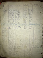
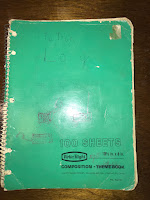
Original log book from
1971.
When I first got into radio, in 1971, I barely knew what I was doing. I had done some shortwave DXing with my GR-81, but that rig worked much better on the AM broadcast band than anywhere else. Just before labor day of 1971, I put up my first outdoor antenna. 

Previously, I had just used a spool of magnet wire strung around the ceiling of my attic bedroom. This was not a very good antenna. Just before school started in 1971, I bought a 25 foot roll of small speaker wire and unzipped it all. Soldering the two pieces together, this gave me 50 feet of antenna wire, which I strung out the window, across the garage and into a tree at the edge of the yard. 

I was eager to try this new antenna, so I proceeded to tune across the AM broadcast band that evening, and log each station I could. I started about 9 PM, and kept tuning until midnight. The next evening, I continued the process. 

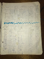
Sep 3 log page.
That first night, I had started at the bottom of the band at worked my way upwards. The second evening, I continued upwards, but then reversed and went lower in frequency. This made more sense to me, and my later "countdowns" that I would make in subsequent years all started at the top of the broadcast band and continued toward the bottom. 

Sep 4 log page.
This event inspired me that for the next several years, I would try to do a "countdown" around Labor Day weekend. It marked the end of the summer, but also the beginning of the radio season. 

I remember it distinctly. I would sit patiently and wait for the AM stations to ID, generally at the top or bottom of the hour. If I got lucky, they would ID sooner. 

Hard to believe that event was over fifty years ago. 


Monday, November 30, 2020

Schematic for the Little 40m Receiver

I'll admit that it has taken far too long for me to publish this schematic. I wrote the original article about a small solid state receiver in January of 2009. I promised a schematic, but I never published it. 

The original sketches of the schematic are too embarrassing to publish directly, so I had to re-draw the schematic neatly.  I started on it last summer, but I finally finished it very recently. 

Just click on the image to the right. 

A couple of notes on the schematic.

The IF Out label on the right side of the page connects to the IF Out label in the lower middle of the drawing. 

I didn't have a 7808, so I used a 7805 regulator with a stack of four 1N4001 diodes that gives about a 7.5 volt supply. You could use a 7808. In fact, I purchased one a while ago, but I've never modified the rig to use it.

You might have to adjust the values in the S-meter circuit if your meter movement isn't a 600-ohm 250 uA device like I used.

I don't have a block diagram, but the sections are straightforward:

  • SA612 Mixer / Oscillator
  • Crystal ladder filter
  • MC1350 IF Amplifier
  • SA612 Product Detector / Oscillator
  • LM 386 AF Amplifier
  • LM 358 AGC Amplifier / S-meter driver
  • 2N3906 Mute driver

I built the rig in stages, starting with the AF Amplifier, then the Product Detector, IF Amplifier, Crystal Ladder filter, Mixer. I then added the AGC Amplifier and the S-meter driver, and finally the mute driver. 

The Crystal Ladder filter is based on 4.915 MHz crystals. The Oscillator is 7 MHz above that, nominally tuning 11.915-12.065 MHz. I've been thinking about adding a switch with a different oscillator and bandpass coil to cover 30m. 

Friday, August 31, 2018

Save WWV / WWVH!

Apparently, the budget proposals for NIST don't include funding for WWV and WWVH. If these budgets go through, then our beloved stations on 2.5, 5, 10, 15, 20 and 25 MHz will go silent after over 98 years of broadcasting.

I can't imagine radio without these stations. There have been countless times I've set my clocks and watch by them. And while the internet and NTP may have largely replaced them for that function, there's no equivalent internet protocol for frequency measurements.

I remember how cool it was late one evening when I could hear both WWV and WWVH on 2.5 and 5 MHz.

I can't imaging calibrating a home-brew radio without the reference signal of WWV or WWVH. I guess there's always CHU, but the frequencies aren't as handy.

I encourage you to write your Congress persons and let them know how important funding of WWV and WWVH are to you.

There's also a White House petition to sign, it needs about 87,000 signatures at the time of this writing.

I would hate to lose WWV and WWVH. Please do your part.

Tuesday, February 28, 2017

The Station Notebook

When I originally set up my station as a novice, I didn't make a lot of notes. I wrote a few things on the back-side of my logbook pages: radios I used, antennas I put up. But, for the most part, I freely made changes to my setup without a lot of documentation.

Some years later, I had a small steno-style notebook lying around, and I used it to record certain information. Like the exact color-code of the RS-232 cables I wired up for my computer. That sort of thing was handy to have written down, because it saved a lot of reverse-engineering later I went to make another cable. But that was about it.

Perhaps a dozen years ago, I read a couple of articles about James Lawson, W2PV, and how he kept copious notebooks about his station. He even solved a sticky problem during a contest, because he kept notes about his antenna installation.

After that, I started writing more things down in my little Steno notebook. Most of it was changes I made to the station -- radios or antenna modifications. Or if something big happened -- like I blew up the amplifier. I recorded a lot more details, and I put dates on everything.

But when I began to spend most of my time out in Floyd County it put my little steno notebook out of reach. I had a new station and I still wanted to keep notes. My solution was dead simple -- I created a text document using TextEdit. I called it Floyd County Station Log.

Looking at it today, it's more like a diary. Each month, I put in a new heading: March 2017. And below that I record anything interesting that I do. I record the things that work, and I also record the things that don't work! If I don't do anything that month, I'll just change the heading to the next month.

The bottom of this document has a list of projects to be worked on. Silly now, since I'm no longer at that QTH: 6m antenna, K9AY controller, 20m and 30m traps for the dipole, tribander-Moxon  times 3 (now that's an interesting project I'll need to write about some day!), remote antenna switch, etc.

This method worked so well, in May 2015, I adopted it for my main station log. Not only did I make new entries, but I also entered all the data from the steno notebook. Plus, I went back through all of my contest comment submissions and recorded all the changes I had made to the station from November 1994 to date.

Today the Gwinnett County Station Log is a reasonably complete record of all the things I've done with the station for the last 22+ years. It has six pages of project notes at the end. Lots of stuff to work on! And, yes, I also have a smaller document for the Walton County Station Log.

I guess my point is that having a station notebook is extremely valuable. It doesn't matter if you use a small steno notebook, a spiral-bound notebook, a composition book with graph paper, a loose-leaf notebook, or a computer document. The important thing is to find a style that works for you to keep notes. After a while, there's just too much to try to remember. So keep good notes.


Friday, September 18, 2015

The Venerable TS-430S

The Venerable TS-430S with AT-250 antenna tuner.
I realized earlier this week that my backup rig, the Kenwood TS-430S, turns 30 years old this month. Yup, I bought that rig back in September of 1985. For the next 16+ years, it would be my only HF rig.   I held on to that rig so long, by 1995, I was already calling it "venerable."

How I got to that point is an interesting story. My original Novice setup was an SB-301/SB-401 combo. In my second or third year of college, I sold my SB-401 to my brother Ben (now NJ8J). I still had the SB-301, and eventually I set it up in one of my college apartments. But I lacked a transmitter.

One summer, I attempted to rebuild my Novice transmitter using a 6GK6 and 6146 design published in the ARRL handbook. I added a lot of extras, like a built-in VFO and a KOX (key-operated-switch), with automatic T/R switching. (the VFO and KOX board were salvaged from a home-brew 40m QRP rig project that I assembled, but never could get to work) I never could get any output from that 6146 rig, and it chirped pretty badly.

Shortly after I finished college and moved into an apartment, I borrowed a friends FT-101E. The rig worked great. Because of my crummy antenna situation, I had a lot of trouble making contacts. Eventually my friend asked for his FT-101E back.

Since he bought the SB-401, my brother wasn't using a Heathkit DX-60B he had, so I borrowed it. I pulled the VFO out of the Novice transmitter, mounted it in a box with the KOX circuit board, a power supply and connectors for the DX-60B. This actually worked! I made a handful of contacts, but again the antenna situation really limited me.

In the summer of 1985, I moved to a new apartment much closer to work. It was two stories tall, and there were a number of trees about 30 feet away from the back. I took a couple of 100 foot spools of #26 wire wrap wire and strung them into the trees from my second-floor shack window, fed from the back of a crappy MFJ tuner with a balun. This formed a crude doublet.

For an operating table, I bought a door, placed it on two short two-drawer filing cabinets, and finished it with stain and polyurethane. I did a good job, because this door is still my operating table to this day in Gwinnett county.

I still needed a rig. I decided I didn't want to fool with tube-type radios any more. (That urge would return later) I wanted something that was all solid-state, had a direct-reading frequency display, supported the new WARC bands, and didn't cost terribly much.

At that time, the top contenders were the Kenwood TS-430S and the Yaesu FT-757GX. Both had a reasonable feature set, and were similarly priced around $600. I don't know what tipped me toward the Kenwood. In retrospect, based on what I know today, the FT-757GX had more features -- it does full QSK and has a built-in keyer, as well as supporting computer control via the CAT system. Computer control would be something I would pine for a few years later when I got into contesting.

Back in 1985, I wanted to get the best deal on my TS-430S, and I must have called a dozen different dealers for a price quote. The deal I found was a TS-430S for about $630, including the optional FM board. I placed the order with my credit card -- and this was perhaps the first time I would go into debt for my hobby.

I didn't do a lot of operating from that apartment, but I did enjoy the TS-430S. The crude doublet actually worked pretty well. I spent a fair amount of time on 30m, which was a relatively new back then, but I also hung out around the Novice bands on 80, 40 and 15m.

I moved to a house in Stone Mountain, GA, and the TS-430S was my main rig. My antennas progressed from a 300 long wire to a loop skywire, to a 125 foot doublet, eventually complemented by a Butternut HF4B beam on a roof tower that eventually gave way to a Cushcraft A3S. I started contesting in 1986 with CW Sweepstakes. The TS-430S paved the way for a whole lot of radio experience for me.

As a rig, the TS-430S is not a bad performer. There are two key deficiencies that were fixed by it's successor, the TS-440S: a) computer control, b) 100% duty cycle. The TS-440S adds a host of other features (100 memories, internal antenna tuner, selectable filter bandwidths, FSK, selectable AGC) Ironically, the TS-440S would be introduced at Dayton in 1986, just a few months after I bought the TS-430S.

CW performance is reasonable, depending on your expectations. There is no QSK, but the VOX operation from the key is quick and reliable. You can at least listen between words. AGC action is fast. The 500 Hz CW filter is a must-have.

SSB works well. VOX is fully adjustable, and the speech processor produces reasonable results on air. Choosing LSB or USB, though selects the slow AGC, which is annoyingly sluggish.

FM is interesting. I played around with 10m FM in the late 80s. There used to be a few guys in the Atlanta area that would hang out there back then. I think it may have faded, along with a lot of 2m FM.

Receiver performance is pretty good considering the up-conversion design and the vintage. There's certainly some front-end IMD, which you hear as a "sparkle" sound, especially on 10m when it is open during a contest. Usually hitting the attenuator knocks that out. The notch filter is pretty good, provided you are only dealing with one carrier. Of course, you have to adjust it manually. Noise blanker is one of the better ones.

Some contesters would be displeased with the manually-centered RIT. Never bothered me. IF Shift can sometimes help fight QRM -- but not in really crowded conditions.

This rig has some features I have rarely used. General Coverage Receive is one of them. Program scan has got to be the most useless of all -- since you have to manually hold the scan if you hear a signal.

I have made a handful of mods to my TS-430S. I did the 10 Hz frequency readout right away. (Why they didn't ship it from the factory this way, I'll never understand) Back when I used transverters for 2m, I enabled all-frequency transmit. Oh, and I did a simple mod that allows the YK-88C 500 Hz CW filter to be used for SSB narrow. This is useless for Phone, but makes easy work for RTTY.

Running RTTY is a mixed blessing. With the 500 Hz filter and the IF Shift adjusted, it does respectably on receive. The slow AGC is a little bit of a problem. Transmitting, though, should be limited to about 50-75 watts. Be sure to turn off the speech processor.

This rig has been with me at five different QTHs, as well as a host of Field Day operations. Although I long ago bought an MB-430 mobile mount bracket, I have never mounted it in a mobile.

Considering all the rapid changes in electronic and radio equipment in the late 70s to mid-80s, what with the transition from tubes to transistors to integrated circuits, plus the addition of new amateur bands -- it is amazing this rig still holds its own. I certainly didn't expect to be using it 30 years later.
Tuesday, November 11, 2014

What Ever Happened to 2m FM?

My first 2m FM rig was the Icom IC-230, like this one.
I was reading an article in a recent issue of QST, talking about the rise of FM in amateur use, and it dawned on me. It's been nearly 10 years since I had a VHF FM radio in the car.

Thirty-five years ago, in September of 1979, I got my first 2m rig -- an Icom IC-230.

My brother Ben, now NJ8J, had gotten a 2m handheld several months before. While home before college, I noticed how much fun he was having on 2m, and I wanted to be part of it as well.

One of his 2m contacts, a gentlemen whose call I have forgotten, had a Icom IC-230 for sale, and the price was reasonable for my college-bound budget. Ben and I went out to his house and came home with the rig. I fashioned a 1/4-wave whip using 19" of coat-hanger wire with four copper wire radials attached to an SO-239 connector. A quick jaunt out the dormer window and the antenna was attached to the roof just above the window.

That old house was in a prime spot for VHF. Right at the top of a hill, it was the highest spot for a couple of miles around. And it didn't hurt the antenna was near the top of the roof.

Propagation that week of September, just before I headed for school in Georgia, was also fortuitous. There was a massive troposphere opening, and I worked FM repeaters in four or five states in just a couple of days. I don't believe I've ever experienced such an opening since then.

Back in the days before frequency synthesizers, the IC-230 was an ingenious design. It used about 18 different crystals in a mixing arrangement that allowed it to generate all 67 of the 30 kHz spaced channels from 146.01 through 147.99, plus the standard repeater offsets of +/- 600 kHz.

Ingenious as it was, this arrangement was obsolete by the time I purchased it. The 2m band had expanded to allow repeater operation in the 144 and 145 MHz sections of the band, and some repeaters were operating on the 15 kHz splinter frequencies, which the IC-230 couldn't access. The rig did have provisions for adding three extra crystals to generate oddball repeater frequencies, as well as a switch position for an external digital VFO. On my college budget, I never could afford these options.

Even so, I could generally find plenty of activity on the main 30 kHz channels. Somewhere along the line, I bought a car, and of course I put the IC-230 in it. My antenna was a home-brew magnet mount made out of a tuna can with a plastic lid, a phono connector with a 19" curved copper wire sticking out of it. Not sure where I got the magnets, but they were strong enough to hold it in place. While the IC-230 was sold long ago, I still have this home-brew mag-mount.

Driving around downtown Atlanta, I often heard other hams complain about intermod from the other VHF signals and the tall buildings. Not with the IC-230. The designers put five helical resonators in the front end to pass the 146-148 MHz signals. Those resonators were like a brick wall to out-of-band VHF signals. In downtown Atlanta, I might hear some picket-fencing, but never any intermod. That's the one feature of that rig I miss.

I eventually traded in the IC-230. I had a Heathkit HW-2036 for a while. I also bought several hand-held transceivers. Today, I have an Alinco DR-570 as well as an old Yaesu FT-227RA Memorizer. Neither of these rigs has seen the inside of a car in over 10 years.

I don't know what it is - perhaps it is the rise in cell phone, but there doesn't seem to be as much activity on 2m as there was a couple of decades ago. Maybe it's just because hams stopped putting rigs in their cars....

Sunday, September 28, 2014

Yes! Found It.

I wrote earlier in the week about a disturbing amount of power line noise. It had sprung up sometime in the last couple of weeks and was a deafening S9++ on 160m. Not good at all for the start of the low-band season.

A day later, I had an opportunity to try scope it out. I found the noise was readily apparent on an AM broadcast radio. In my car, I tried to find the noise, but found it diminished greatly when I left the driveway, and returned once I parked my car near the church. This mean that it was very local, it wasn't something propagating along the power lines in the front yard.

Getting a little portable broadcast radio, the noise was quite loud in the shack, but diminished as I walked to the church. This meant the noise was likely coming from the parsonage itself.

Next step was to flip every breaker off in the parsonage as I listened to the radio. Of course, once I flipped the very last breaker, the noise disappeared. Turning all the other breakers back on -- no noise.  Then it was a matter of deducing what was being powered from that circuit breaker.

The circuit breaker in question, number 15, was powering a few outlets that supplied power to my internet router and other pieces of equipment on my wife's desk. A bit more unplugging found that the parsonage wiring wasn't the culprit, but something plugged into the wall. A bit more, and the cause was found -- it's a wall wart power brick that powers my AT&T Microcell.

When we got the Microcell back 3 years ago, the coverage underneath the parsonage's metal roof was extremely bad. Since then, it has gotten a little better. Until I can replace the bad power brick, we can live without the Microcell.

And no more noise on 160m. Hurray!

Thursday, September 25, 2014

Crap. Line Noise

OK, perhaps I could use stronger language. Here it is, the start of the fall low-band DX season, and I have line noise.

In the three years I've been out here in Floyd county, the low bands have been very quiet, so it has been easy to hear other stations. You'd think being out in the country like this it would stay that way.

Well, something has changed in the last week or two. On 160m, I'm reading constant line noise 24/7. In an SSB bandwidth, it is S9+20. In a CW bandwidth, it is still S9. Terrible. On 80m, it is a little better, about S7 in SSB, and S5 in CW -- about the same level as the atmospheric noise. Above 80m, I don't notice it, really.

It's been very dry, as is typical of this part of the fall here in Georgia. However, even a recent downpour didn't silence the noise.

This is very bad. I guess I'll have to hunt down the source and tell Georgia Power about it. I sincerely hope they can fix it before the ARRL 160m contest.

Wednesday, April 23, 2014

Fixing the K2/100, Again

D16 and D17, plugged into machined socket pins.
About a year and a half ago, I wrote about repairing my K2/100. Part of the fix involved replacing diodes D16 and D17 on the KPA100.

The same week I bricked my K3/100, I found the K2/100 was acting up. I was going to grab it in case I needed to send the bricked K3 back to Elecraft.

But, before I did that, I spent part of an evening trying to work some of the W1AW-portable operations. I didn't have a lot of luck. The power output seemed erratic on some bands, and on others, the automatic antenna tuner couldn't seem to find a match.

Seems to me I'd seen this behavior before -- when the SWR bridge diodes, D16 and D17, had undergone a soft failure. I figured that if this was going to be a regular occurrence, I ought to make the job easier.

I found an old machined-pin IC socket and carefully clipped away the plastic to reveal four individual pins. Actually, it was more like six pins, since I dropped one and couldn't find it under my desk. And another one I hopelessly bent. Fortunately, these things come packaged with fourteen to sixteen pins at a time, so I had plenty of spares.

A bit of work with a screw and nut driver released the KPA100 board from the heatsink. Pulling the old diodes from the board is a bit of a delicate operation, since you want to be carefully not to mess up the board traces. However, with the socket pins, this is the last time you'll do this.

Soldering the socket pins in place is one of those operations that would be easier with four hands. Even holding the board in a small Panavise, I needed one hand to hold the machine pin with pliers, one hand to hold the soldering iron, and one more hand to hold the solder. That's one more hand than God gave me, but somehow I managed.

Once the pins are in place, it is a simple matter to trim the diode leads and bend them down to fit the socket pins. I had ample spares from my earlier purchase.

I checked the diodes with my DVM. (Oh, I should mention that I discovered my 20 year old Radio Shack DVM bit the dust. Apparently one of the AA batteries inside managed to get enough corrosive goo on the circuit board to render it irreparable. So, I had to go out and buy another DVM. It would have been nice to know this before the last hamfest, as these types of devices can easily be had for a few dollars. As I was, I bought a cheap unit at the local Home Depot for about $20. More than I wanted to spend, but I had it in my hands immediately.) These diodes didn't show any obvious odd behavior. The forward voltage was a little off, and the reverse voltage was at the limit, just like you'd expect.

Nevertheless, I put new diodes in and ran the calibration procedure for the SWR bridge. Not having a dummy load handy (something else I left at my other QTH), I used a 40m antenna that was a pretty good match. After calibration, the K2/100 seemed to work as expected.

I'm surprised how sensitive these diodes appear to be to static discharges. I'm going to have to make sure I keep the rig antenna grounded when I'm not around.


Friday, August 2, 2013

The Elecraft K3 is a Joy on RTTY

K3 - Right in the operating position
I built the K3 just after Christmas. Since then, it has been a joy to operate in many ways. Having just completed my third RTTY contest this year, I'm especially pleased with how it operates on RTTY.

Although I operated packet radio back in the 1980s, I never got a make a RTTY contact until 2005 - using my Elecraft K2. I built an audio interface using a couple of audio transformers and some resistors.

In many ways, the K2 is a great radio. Gary Breed K9AY told me that the K2 was, "a simple radio, superbly executed." While I do enjoy the K2, it is not at it's best running RTTY or any other digital mode. It suffers several limitations:
  • Duty Cycle - The K2 is designed for a 50% or less duty cycle - CW or SSB. Without supplemental cooling, you can't run the K2/100 much more than about 25-30 watts. I added a small fan on top of my K2, and could safely run 50-75 watts of RTTY without overheating. The K3, of course, is a 100% duty cycle rig - no problem running 100 watts for hours. The case doesn't even get warm.
  • Tuning Rate - Because of it's design, the K2 tunes in roughly 9 Hz steps. While the display shows the nearest 10 Hz at all times, the firmware selects the closest tuning point. As you turn the dial, it's not entirely smooth, sometimes jumping twice as far. With the finicky tuning of RTTY signals, you'll notice this.
  • Frequency Readout - I put this one in my K2 Wish List. The K2 frequency doesn't account for the mark frequency, and thus reads 1-2 kHz high, depending on what audio tones you are using. While some contest software can compensate for this, the K3 works correctly by showing the mark frequency on the display.
  • Variable Transmitter Gain per Band - this is the most annoying thing about using the K2 on RTTY. Because of the way the K2 transmitter gain control system works, you have to adjust your audio levels on each band -- very high levels on the higher frequencies, and extremely low levels on the lower bands. Every time you change bands, you must adjust the transmit audio level. Every time. The K3, on the other hand, calibrates itself so that it has the same gain on every band. 
But the best part isn't that the K3 can run flat out 100 watts, tune smoothly, display the right frequency, or make it so you don't have to mess with the transmit audio level in the middle of the contest. These other features of the K3 really enhance RTTY operation:
  • Variable-Bandwidth IF - My K2 is programmed with a variety of bandwidths for RTTY: 1000 Hz, 500 Hz, and 300 Hz. But this isn't nearly as convenient as being able to select any bandwidth from 100-4000 Hz. On a quiet band, a bandwidth from 600-800 Hz works well. When the QRM gets tough, pulling down to 300 Hz puts it in its place. The K3 allows you to pick exactly the right bandwidth for the situation.
  • Dual Passband - RTTY contests can get downright ugly. Sometimes strong stations are interlaced on top of one another, so the mark or space frequency of one station is right between the tones of another station. This situation does no good for anyone, as it makes it nearly impossible to copy either station. I'm convinced that this is largely due to the over-use of  dual passband filtering. This type of filter puts a huge notch between the mark and space tones. It's not useful for S & P work, because if you are slightly off frequency, you won't hear stations. And, it's not terribly useful for calling CQ, either, since someone can easily move in between your tones and you won't hear them. However, every once in a while, this filter makes the difference between completing a QSO and losing one to the QRM. Just don't use it all the time, OK?
  • Fine Tuning - While the K3 tunes in perfect 10 Hz steps, you can select fine tuning mode with 1 Hz steps. I used this all the time as default for CW and RTTY and move it. It makes tuning across the band take longer, but it's easy enough to switch to 10 Hz steps when you need to.
So, every time I changed bands, tweaked out QRM with the filter or passband tuning, marveling at how cool the rig is running pumping out 100 watts hour after hour or just simply tuned stations in -- I'm consumed with joy over this fine radio. Definitely worth it.


Sunday, February 24, 2013

Samlex SEC 1223

Unit #2 - before modifications.
I guess you can say I'm pleased with the Samlex  SEC 1223 power supply. After all, I own three of them.

Back in 1988, I bought a CB-grade 12 volt linear power supply capable of 25 Amps output. It needed a little work to function correctly, but it powered my venerable TS-430S and later the K2/100 for 19 years. It finally went west one day when the power transformer opened in the primary winding.

Soon after, I was hunting for a replacement at a hamfest. I found a Samlex SEC 1223 that fellow had replaced with an Astron SS-25M. Used, the price was right, at about $50. The unit is impressively small, and it had no trouble powering the TS-430S, K2/100 or K3/100 to full output on every band.

However, this unit had numerous spurs on 160m. I found the loudest one was around 1845 kHz, about S7 on the very scotch K2 S-meter. Note that the location and strength of the spurs varies with the supply load. Using snap-on ferrite cores as an experiment, I found that putting them on the power cord and the output power leads led to a reduction in the spurs.
Unit #1 - showing seven FT50-77 ferrite
toroids on power input leads.

My first modification was to de-solder the white and black power cord jumps inside the unit and slip on seven FT50-77 toroids. That reduced the spur to about S5.

Unit #1 - Output lead modifications.
I then made a modification designed by ZL2DF and published by N0SS. My unit was different from that of ZL2DF. It did not have the screw / compression power terminals. Instead, my unit had binding posts soldered directly to spade terminals on the PC board.

I pulled out the PC board and removed the spade terminals. I replace them with 16 gauge wire fed through eight type 43 ferrite beads. The wire is a bit small, but is the largest that will fit through the beads. The output terminals are bypassed across each other and to ground with .1 50v multi-layer ceramic caps.

With this change the 1845 kHz spur was just audible. Atmospheric noise covers it up at night.

Last year, I found another one of these gems at a hamfest for $20. Took it home and sure enough, a few spurs on 160m. Made similar modifications -- toroids on power leads, ferrite beads on output, caps across output terminals. Again, the spurs don't disappear, but are much less pronounced.

Unit #3 - perhaps only needs power input filtering?
This year -- you guess it -- I found another one for $5! This unit is a little different, as it has a large ferrite bead with both power leads run through it to the compression terminals. Perhaps it will only need a big of work on the power leads. We'll see when I can get it on the bench.

These are very capable little power supplies. They are easily able to power a 100 watt transceiver, and with a little work, they are quiet enough for MF and HF use.


Wednesday, January 9, 2013

Straight Key NOT!

Since I was thinking about Straight Key Night before, you might anticipate I would have an extensive operating report of the Homebrew 40m Transmitter and Receiver. Well, not exactly....

I did go and review the rules. There are no prohibitions against using electronic keyers. Indeed, the guidelines state "This 24-hour event is not a contest; rather it is a day dedicated to celebrating our CW heritage." I certainly consider my nearly 34-year-old Mini-MOS keyer part of my CW heritage.

So, that was my plan -- to cheat on Straight Key Night and use my keyer. 

I was busy during New Year's Eve, so I went out on the morning of New Year's Day and hooked up the keyer to the 40m Transmitter. With the spotting function, it appeared to work. The keying was a little soft, but I was able to find my transmitting frequency with ease. I tried two or three crystals, and then I noticed the oscillator wasn't stopping. If I unplugged the keyer and plugged it back in, I could send one element, and then it would stick on. Then it stopped working altogether.

At this point, I was sort of in a panic. I pulled the cover off the keyer and looked inside. What I saw next set me back a moment -- there was no battery in the keyer! I had been using the keyer solely on the stored power in the electrolytic capacitor for about five minutes. Now that is a low-power station accessory!

I scrounged up a 9 volt battery and verified that I had not fried the 30+ year old CMOS chips. However, it appeared that the CMOS gates had enough leakage that it would not reliably cut off the 6CL6 oscillator. 

The original Mini-MOS design keyed through a PNP transistor in order to work with grid-block keyed rigs -- with a negative keying voltage. That worked great with my SB-401 and later with a DX-60B and the FT-101E that I borrowed. When I bought a Kenwood TS-430S in 1985, it had a positive keying voltage. I simply removed the PNP transistor and connected the keying line directly to the CMOS 74C02. Since it worked, I kept using it.

I think the original problem was there are no free gates in the seven chips that make up the keyer. In order to drive a NPN transistor or enhancement-mode FET to key the transmitter, the keying sense has to be reversed -- instead of bringing a positive voltage to ground, we need to go from ground to a positive voltage for the base / gate of the transistor. In retrospect, it would have been easier to have left the PNP transistor in place, use it to drive an NPN transistor or  FET.

A quick look in the junk box revealed some 2N7000s -- an excellent enhancement-mode FET to key the transmitter. (The K1EL keyers use this same device) I just need to dig up a PNP and some resistors. Ah, a project for another day.

Oh, and what about Straight Key Night? Well, since I had just gotten the K3 going, I decided to play with it instead of SKN. I ended up working DX spots on 12 and 17m, including working VP2MRV on RTTY using the K3's FSK D CW to RTTY mode. Cool.

SKN? Maybe next year....

Saturday, December 29, 2012

K3!


K3/100 build and under the Christmas tree.
I have the best wife in the entire world.

When it came time to make our Christmas lists this year, I had mentioned that it had been ten years since I bought my last ham transceiver -- I finished the KPA100 for the K2 in the fall of 2002. And while it might be time to look at something new, modern transceivers are not cheap. In the end, I decided to ask for contributions toward the "K3" fund -- money I would use to buy an Elecraft K3 at some point in the future.

Before Christmas, my wife had hinted she had gotten me something expensive. She would tease me that she had purchased a Cessna 140 or a Harley-Davidson. She did it often enough I wasn't sure what to believe.

Inside these boxes is a bit of joy.
However, due to some shipping difficulties, my present didn't arrive until three days after Christmas.

Needless to say, I was surprised to open the box find a stock K3/100!

She had the presence of mind to get me the unassembled version, instead of the factory-built. While it's a bit more work, I really enjoyed assembling my K2/100, so I figured I'd get some enjoyment out of this.

Biggest problem, though, was where to build. The Micro-Shack is, well, micro. The entire desk surface is barely 5 by 2 1/2 feet. Most of my tools are still down at the QTH in Gwinnett county. Nevertheless, I figured I'd do what I could with what I had, rather than wait a week or so until I could get to my big workbench.

K3/100 goes together on the world's smallest workbench.
As it stands, I had enough room for the job.

It was already late in the day when I got started, so I decided to forgo the Elecraft-recommended inventory. I've built a number of their kits, and I can't say I've ever been shorted a part. Indeed, they always seemed to ship me extras. In retrospect, this wasn't such a bad idea. If you've never built a kit before, inventorying the kit is a great idea.

Since all the boards are pre-assembled, there's no need to warm up a soldering iron. However, there's plenty of mechanical assembly. I thought it was weird that Elecraft has one put the left and right side panels on, only to have you remove them a few steps later.

I had never really seen the insides of a K3 before, and the pictures don't do it justice. In some ways, it really is like an over-sized K2, with the mechanical rigidity coming from the main board. Once you get the casing on, it's really pretty rugged.

Initial power-on successful.
Assembly was pretty much a joy, except for the limited work space. I had a great sigh of relief the first time I powered the K3 on, since it was clear I hadn't messed it up somehow.

I did have one item I did mess up during assembly. It was the KREF3 board. The instructions indicate you are to cut off any leads that might be longer than certain components on the board. I found a through-hole connector lead that I thought was a bit long, and when I tried to trim it, I also managed to bust capacitor C2 off the board. Fortunately, this component isn't used for anything critical. My guess is that it is used for FM only, but there's not really any documentation as to what the TXMIXFIL signal does. I've already contacted Elecraft support as to how they suggest we fix this.

After about six hours of work, my K3/100 was all assembled and calibrated. I only ran into one issue -- I had no dummy load to perform the Transmitter Gain Calibration. I ended up doing the calibration manually using the antennas I have on hand. Not perfect perhaps, but it will do until I can get my hands on a dummy load.

K3/100 assembled and operational.
Now that it's assembled, I have to go an order the other options I need. Unfortunately, the KAT100 doesn't work with the K3. I went ahead and used some of that "K3 Fund" money and ordered the KAT3 antenna tuner as well as the KXV3A transverter adapter. That should do me for quite some time.

Now, I need to sit back and read this thick operating manual so I know how to use my new rig! See you on the bands.


Tuesday, December 25, 2012

Thinking Ahead to Straight Key Night

These two rigs sit in my shack all year, but I really only use them on new year's day. I'm talking about my home brew Novice Transmitter and Receiver.

Practically speaking, the transmitter isn't terribly useful. Being crystal controlled, you can't hunt around the band and answer someone -- you must call CQ. And it only covers 40m. 40m is a great band, but not everything happens there.

The receiver would be more practical to use -- it's a pretty nice superhet, with a narrow CW filter. But, really, it's designed for use with the transmitter, so it too, sits idle on the shelf.

2013 will be the seventh year I've operated Straight Key Night with this transmitter. Frankly, I'm considering cheating. Instead of using my old Japanese J-38-style clone, I'm thinking of using the Mini-MOS keyer. The whole idea of Straight Key Night is to return to our roots. Why not use this over venerable equipment? I also wonder how the transmitter will sound being keyed electronically, instead of mechanically.

If I do end up using the keyer, I'll have to disqualify myself.

Wednesday, September 12, 2012

K2/100 Fixed

Don Wilhelm W3FPR gave the me answer for fixing my K2/100. He suggested I replace D16 and D17, as they may have gone bad without failing open or shorted.

It took a while to get the parts from Mouser. But these 1N5711 diodes were only $0.10 apiece. So, I bought 10 in order to have some spares.

Replacing D16 and D17 did the trick. I managed to test one of the diodes I removed (the other was destroyed in the desoldering process), and it showed a nearly correct forward voltage on my DVM, and about 3 times that value when connected in reverse. The diode action of the part was clearly compromised. A new part gave a low forward voltage, and an open when connected in reverse.

I suspect these diodes, and possibly the EL5146C might have been damaged by a stray static discharge sometime in the last year. Perhaps a good thing to have on hand -- although Don did indicate that 1N4148 diodes would work OK as a temporary substitute.


With the new diodes in place, the SWR Null Adjustment went well, giving a clear null down below 100 mV. More importantly, it read an SWR of 1.0 on all bands.

The rest of the alignment went smoothly, and the rig appears to be producing the correct power levels on all bands. Made a quick contact with HA8RM on 80m to confirm the rig is working again. I think it is cured.

Sunday, September 9, 2012

Fixing the Broken K2/100

Well, it's been slow going for my ailing K2. I put the tested U5 - 78L05 back in the board and cut pin 7 of U6. The KPA100 once again responded to the main K2.

I replaced U6 with a machine pin socket, and after waiting another week, I finally got the part from Elecraft. 

With U6 replaced, I went through the KPA100 alignment steps. First problem was the SWR Bridge Null Adjustment. While I could get a clear null, the display never showed anything less than 1.1 SWR on 40m. 

Next to the Power Calibration. This went fine as well, but when I checked the SWR on all the bands, I received a 1.8 SWR on 80m, and 2.6 on 160m. The highest bands gave a 1.0 indication, but most of the others were 1.1, just like 40m.

I double-checked my dummy load with my external watt meter. It appears they are 1.0 on all bands.


A bit after this, I did some full-power tests:

* 40m - K2 indicates about 70 watts (7 bars), but the external watt meter shows 100 watts
* 80/160m - K2 indicates about 50 watts (5 bars), and sometimes I get a Hi Cur warning. The external watt meter shows 100 watts, or perhaps a little more.

Something is obviously wrong with the power measurement circuits here.


Elecraft suggests that the D16 and D17 diodes are "half bad" -- that is they have been damaged enough to change their characteristics, but not enough to fail open or shorted. Next step is to replace them.

I just got the parts from Mouser this weekend. We'll try more repair work this week. It would be very nice to get the K2/100 up and running again. I'm guessing there might have been some damage from an electro-static discharge of some kind. 

Friday, August 3, 2012

Broken K2/100

OK. At least I know what's wrong. It appears that one of the chips on the KPA100 fed by the 78L05 has failed and is drawing so much current that the regulator only puts out about 1 volt.

It isn't U1 -- the PIC chip that runs the KPA100. That one is at least socketed and was easy to remove and test with it out of the circuit. And it isn't U3 -- the 78L05 regulator. I pulled it off the board and tested it, it works OK.

It is either U4 -- the MAX1406C chip, or U6 -- the EL5146. My bet is on the EL5146. Now to order parts....

Saturday, February 25, 2012

Straight Key Night 2012

Novice transmitter, receiver, and the venerable TS-430S with
the AT-250 auto antenna tuner round out the operating bench.
Yes! Straight Key Night. 2012 makes the sixth year in row I have operated this event. Once again putting  the "Novice" Transmitter on the air, paired with the very capable superhet receiver.

This year, I didn't have any technical problems with either the transmitter or receiver. In fact, they worked pretty much flawlessly (other than the fact that I was missing the stereo to mono adapter for the receiver and had to copy everything with one ear). The interesting thing this year is where they were.

Of course, I had set this equipment up in the Micro-Shack. While not much more than a storage closet, it actually does have just enough room to set up and operate a modest amount of radio.

With a little bit of help from a space heater, it was actually quite cozy during the January 1st operating event. Not much in the antenna department. I believe I favored the low 80/40m dipole rather than the R7000.

As I've written before, being crystal controlled means you have to call CQ. After making a couple of contacts, I decided it would be fun to make at least one contact with every crystal in my arsenal. My ten crystals span the 40m band from 7001.25 to 7121.1 kHz. Some of the frequencies are quite popular, whereas others are pretty far away from heart of SKN activity. Oddly enough, it was the popular frequencies that were the hardest to complete -- they were almost always in use.

I was successful in not only making at least one contact on 7001.25, 7006.7, 7010, 7038, 7042, 7047, 7050, 7061.1, 7075, and 7121.1 kHz, but also making one contact on 10108 kHz. I had just gotten two crystals for 30m this past Christmas, and they tuned right up in the "Novice" transmitter. Of course, the little receiver couldn't be used, so I used the TS430S for that role.

Fifteen total contacts, to twelve different states: VA, MI, FL, GA, TN, TX, PA, MN, IN, AL, NY, NC. My best ever SKN outing.

Sunday, September 4, 2011

40 Years of Radio

September 3rd brought forth some fond memories for me. It stands out in my mind because of the evening of September 3rd, 1971. I received my first radio, a Heathkit GR-81, Christmas 1970. My first logbook entries are from January 9th, 1971, since it took us a while to build, especially considering that the band "A" coil we got with the kit was defective.

For many months, I used the GR-81 with nothing more than a bit of magnet wire wound around my attic bedroom. This worked, but it wasn't very effective. I listened to some local AM stations, and a few shortwave stations. The GR-81 wasn't very sensitive on band "D", where most of the shortwave broadcast bands are, so I concentrated on broadcast band DXing.

With the summer ending and school about to start, I managed to take a trip to the electronics store and buy some wire. I believe at that time, I bought a 25 foot spool of very small speaker cord and completely unzipped it. In my youthful frugalness, I had computed that this resulted in a cheaper acquisition of 50 feet of wire than buying a 50 foot spool outright.

That 50 feet of wire went out the window of my attic bedroom, across the roof of the garage, and was anchored to a climbable tree on the other side of the yard. In retrospect, it couldn't have been horribly effective -- it was too low to the ground, being only 10-15 feet high for most of it's length.

However, it was outdoors -- this being my first outdoor antenna. The results were pretty dramatic, compared with the indoor magnet wire. That evening, I started at the top end of the AM broadcast band (band "B" on the old GR-81), and worked my way toward the bottom. I must have logged about 40 different stations, many of them new.

This experience made an impression on me. For the next several years, I always attempted to do this AM "countdown" around labor day weekend. In addition to signaling the start of the school year, it was also the start of the radio season.

It's hard to believe it's been 40 years. I still have that radio, and it's still in good working condition. And somewhere in my files I have that first logbook.

Saturday, January 8, 2011

Straight Key Night 2011

The operating desk set up for SKN 2011.
Since building the "Novice" transmitter in December 2006, I have enjoyed operating it every Straight Key Night since. It's probably the only time I have this transmitter on the air all year, which is something of a pity, I suppose. 

The transmitter is paired with an equally interesting receiver. The two work pretty well together for 40m contacts

About a week before SKN, I fired up the transmitter to confirm everything is ready and found I could get no power out. I could hear the oscillator pretty well, but there was no grid current and no plate current.

Opening up the base plate immediately showed the problem: a 2.2 k 2 watt resistor in the oscillator plate circuit had overheated, and it had unsoldered itself from the terminal strip on which it was mounted. I replaced it with a 3.3 k 2 watt resistor, mainly because it had shifted in value to over 4.5 k! After that quick fix, the transmitter worked as it should.

This year was fortunate that I had my pick of operating time for SKN. As you can see in the picture, I had merely to ignore the modern equipment on the desk and enjoy exercising the homebrew year with my 35+ year old Japanese J38 clone key.

One of the consequences of being crystal controlled in the modern era is the certainty you must call CQ. This was not a problem this year at all. With 50 or so watts out, I had no trouble getting answers on my dipole. In fact, several times, I was called after finishing up a QSO.

My biggest difficulty was my arm kept getting tired. After about an hour of QSOing, I needed to take a short break to let my arm rest. Using a straight key is a lot of work.

In all, I worked an even dozen contacts. Six of those were stations in Texas. I enjoyed working Bob, KE5LYW, who I found out was a fellow pilot. I also had a great QSO with N4HAY, who was using a homebrew single-tube 6L6 transmitter running about 2.5 watts.

Close up of the homebrew receiver and transmitter. Note the
convenient location of the crystal holder this year.
Attentive readers should notice the transmitter sports a new front panel feature -- a crystal socket. This is much easier than reaching around the back of the rig to plug in a crystal when changing frequencies.

Only glitch I had was a bit of stability problem with the receiver. On a couple of frequencies, it would drift around a bit when the headphone cable was moved. If you note the very long set of adapters I used for the headphones, that may have contributed to the problem. I'll have to sort that one out for next year. Other than that, the receiver was a real pleasure to listen to, most likely due to the addition of a few capacitors.

2011 was a great outing for this homebrew gear. SKN is always a blast, and  a dozen contacts this year beats any previous year. Join me on the air next year.