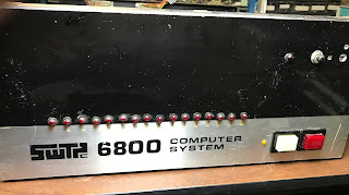
After I completed the SWTPc CT-64, I ordered the SWTPc 6800 computer system in November of 1977. How much memory to order was a consideration. The original kit had the MP-M board with only 2 KB of memory. SWTPc changed this earlier that year to add an MP-MX expansion for a total of 4 KB.
I wanted to run BASIC, plus the co-resident Assembler / Editor (called Co-Res), and this required 8 KB, plus space for programs. To basic kit, I added two MP-M boards. But, I did not order the MP-MX 2K expansion kits. I figured I could purchase the 2102 1Kx1 static RAM chips cheaper somewhere else.
Design
The design of the SWTPc 6800 Computer System results from the MIKBUG ROM. Motorola developed MIKBUG to run a MC6800 evaluation kit. The essential features of the SWTPc system are drawn from this evaluation kit. The ROM resides at address E000, 128 bytes of RAM at A000, and a serial device at address 8004.
The serial device is worth mentioning. For the original evaluation kit, the MC6850 serial device wasn't ready, so Motorola shipped the MC6820 parallel interface adapter (PIA), a bit of divider logic and used software to "bit-bang" all serial communications. SWTPc offered two serial port boards, the MP-C and the MP-S. The MP-C uses a MC6820, while the MP-S uses the MC6850 asynchronous communications interface adapter (ACIA). MIKBUG requires the PIA, so that's what the MP-C uses. This means that the original 6800 computer system cannot receive any characters from the console terminal unless the CPU is actively polling the MP-C I/O board.
The resulting memory map makes perfect sense for an evaluation kit, but left something to be desired as the system grew:
- 0000-7FFF - available for RAM (32 KB)
- 8000-9FFF - 32 bytes for the 8 I/O slots (4 bytes per slot) repeated
- A000-BFFF - 128 bytes of ram repeated
- C000-DFFF - available for RAM (8 KB)
- E000-FFFF - 512 bytes of MIKBUG ROM repeated
Back in 1975, 32KB of memory space seemed enormous. SWTPc recommended only four 4K boards be installed, based on power supply considerations, which topped out at 16 KB. Later, it would become a serious constraint.
Building
The 6800 computer system kit consisted of several sub-kits:
- MP-B Motherboard
- MP-P Power Supply
- MP-A CPU Board
- MP-M + MP-MX 4K Memory Board
- MP-C Console Serial Port Board
- Metal chassis and case to house the computer
After my experience with the CT-64, I was prepared for SWTPc's minimalist assembly instructions.
 |
| MP-B Motherboard |
MP-B
The MP-B was straightforward, although there are nearly 600 connections to solder the bus pins to the heavy bus traces. That was a lot to ask for my 25 watt Weller soldering pencil. The motherboard design has some decoding and buffering logic to separate the seven 50-pin main slots from the 30-pin I/O slots.
(In the picture, you'll note that I have replaced the original nylon spacers with #8 screws. SWTPc used nylon spacers that clipped into chassis bottom and allowed the MP-B to snap in. Those goofy nylon spacers never worked well and often would come loose from the chassis bottom. There's also some additional logic that enhances decoding -- more on that in a future article)
MP-P
I struggled a bit with the MP-P power supply. It had a lot of heavy wiring and board traces. But it is simple and went together quickly.
MP-A
 |
| MP-A CPU board |
The heart of the whole computer system is the MP-A board. Compared to later CPU boards, there's quite a few discrete components on this board, related to the clock drivers and 555 reset timer. Given my experience with SWTPc kits, it wasn't difficult.
(You might notice my board is missing a few things - like the MC14411 chip and its associated crystal as well as the heatsink on the 7805. These components moved to other projects when the board was retired)
MP-M / MP-MX
 |
MP-M 4KB memory
boards |
The MP-M boards with the MP-MX expansion were the most dense. They have 32 total memory chips, plus seven other integrated circuits, two voltage regulators and a handful of discrete components, all on a 5 1/2" by 9" board. It was a lot of soldering. I did this twice, using parts from the second MP-M kit to act as the MP-MX kit.
A few weeks later, I built the third MP-M/MP-MX, using 2102 chips I ordered by phone. It was cheaper, but not by a lot. There were a few other components for the MP-MX I either obtained from my junk box, or bought locally. You can tell that board by the yellow disc ceramic 0.01 uF capacitors.
(In the photo, these boards are missing components, too. The molex connectors are missing from the center board, and the two top boards have donated their heatsinks as well. If you look closer, you'll find a few memory chips that are socketed or are mounted on socket pins. All these chips failed in the first couple of years of use and had to be replaced)
MP-C
 |
| MP-C board, modified |
The MP-C was easy to build by comparison. Generally the I/O boards are really simple. The MP-C had nine integrated circuits, but three of these are six-pin opto-isolators.
This board was designed to support RS-232 connections, as well as 20 mA current-loop interfaces that were typical of mechanical teletypewriters.
(In the photo, the MP-C card has been modified into an MP-S type card using a MC6850 ACIA. The components related to the 20 mA current-loop interface have been removed, as well as the clock divider circuits)
Debugging
The big challenge for this kit was making it all work. Yes, I had a few solder-bridge problems with the CT-64 kit, but I managed to puzzle them out. It was easier where I could see things on the screen.
For the SWTPc 6800, this was harder. A lot of the system had to work to get the MIKBUG asterisk "*" prompt to show up. How as a kid who is not even 17 years old and owns no test equipment other than a cheap Volt-Ohm Meter going to do this?
I was lucky my father worked for a local college and they allowed me to borrow a dual-trace oscilloscope for a few weeks. This allowed me to track down my problems. I was experienced in building enough that I managed to avoid obvious problems like putting components in backwards, or putting the wrong components in a spot.
You'll note most of the integrated circuits in the SWTPc kits are not socketed. Sockets were considered optional for most components. The MP-A board has sockets for four chips: MC6800, MC6810, MC6830 (MIKBUG), MC14411. The MP-C board has a socket for one chip: MC6820. There were no sockets supplied for the MP-B or MP-M/MX boards. Some builders opted to supply their own.
Without sockets, it was important to place components correctly. Unsoldering misplaced components was not a pleasant experience, and it risked damage to the board.
That said, virtually every problem I encountered was either due to a solder bridge, or an unsoldered connection. The SWTPc boards had no solder mask (another cost-saving measure), so making accidental bridges was easy. I found solder bridges on the MP-A board, on the MP-B board, and several on the MP-M boards.
Indeed, getting the memory boards to work correctly was enough of a challenge that it made me appreciate memory test programs. Some simple tests won't find memory convergence problems.
The SWTPc 6800 computer would function with only the MP-A and MP-C boards plugged in. The MIKBUG ROM monitor could be used to enter short machine language programs into the 128 bytes of scratch memory at A000. This made it easy to test the other components, such as the MP-M boards.
The Unit
The resulting unit is a smart-looking turnkey box without any flashing lights. (Mine has been modified with 16 LEDs and a few other holes on the front panel, but I'll tell that story later) It came with aluminum angle trim, but I tended to leave it off. I generally had my hands in and out of the box so often I didn't even screw the lid on.
On the original kits, the back panel had four large holes which passed all I/O cables. In later units, SWTPc added punch-outs for DB-25 connectors for serial devices. Mine has four punch-outs arranged in two horizontal groups just inside the two outermost holes. Other units have four punch-outs in a line above the holes. Other builders have modified their back panels to add other connector types.


