Showing posts with label 6m. Show all posts

Saturday, August 30, 2025

W5WVO 6m Beam Project

W5WVO clone construction so far.

I wrote earlier on my purchase at the Dalton, GA Hamfest of the 6m Mystery Beam. It clearly formed some kind of antenna, given the lengths of the elements. But I had no clue how those elements were intended to be positioned on the boom -- and even if I did, I had no idea what kind of performance to expect.

Course of Action

Unsure of what to do, I asked the folks on he SEDXC mail reflector. Joe Subich, W4TV suggested that I use the components to implement the W5WVO modification of the A50-5S, or perhaps re-create one of YU7EF's five element designs for a 4.5m boom or 4.15m boom

Choosing between these options was difficult. What I had wasn't a A50-5S, so the W5WVO medication wasn't straightforward. And the YU7EF designed were even further afield from my starting point.

I decided to adapt my tubing collection to W5WVO's design. 

My elements were too short, they'd need to be extended. But, it isn't as simple as just matching the length W5WVO specified -- the taper schedule is different. 

The A50-5S and the W5WVO designs use 48" of 3/4" tubing in the center extended with 5/8" tubing to the element length. My tubing is 3/4" the entire way. I'd need 5/8" extensions, but how long?

Answering that question required modeling.

Modeling a Solution

As a Mac user, I use CocoaNEC with the NEC 2 engine. It's pretty sophisticated, actually, but getting good results requires using the NC modeling language, which can be a bit tedious. 

My first model was W5WVO's design using the normal taper schedule - inner 24" of each half element are 3/4" with the rest being 5/8". Results were very similar to, but not exactly the same as W5WVO's article. (Part of the reason is W5WVO used NEC 4 engine) But what I had was close enough.

Second model used the 3/4" element lengths I had, spaced according to the W5WVO design. The results were akin to the W5WVO, but with significantly worse F/B.

Third model used the same 3/4" element lengths, with 5/8" extensions on the tips of each element. Because of the different taper schedule, I experimented using a different percentage of the W5WVO dimensions. Lo and behold, at 80% extension length, I modeled something very, very close to the W5WVO design. 

Reflector with
5/8" extension.
The extensions needed on each end are short:

  • Reflector - 2.5"
  • Driven Element - 0.75"
  • Director 1 - 1.75"
  • Director 2 - 1.375"
  • Director 3 - 0.25"
I added about 3/4" for overlap inside the 3/4" tubing. I secured the extensions using 1/8" Cherry pulled rivets. These aren't ordinary "pop" rivets. Ordinary pop rivets are just a hollow aluminum tube. These leave a steel mandrel filling the tube -- a solid, structural connection.

Building

Extensions on each element.
First step involved cutting the extensions and riveting to each element. I used two rivets on opposite sides. On the D3 element, with the very smallest of extensions, I ended up with one rivet because I broke my #30 drill bit. 

Second step would be to hang the elements on a boom. Oh, wait, I need a boom!

The parts I bought at the Hamfest had three segments of 1" Aluminum pipe which was reinforced by a 13 foot piece 3/4" pipe. None of this fit well together. And the diameter was somewhat small for a 20 foot boom.

I had a 7 foot piece of 1-1/2" tubing I replaced on a Cushcraft A3S. I also had a 12 foot piece of 1-1/2" tubing. Together, they would be 19 feet. The last 10" of the 7 foot tubing had a crack, so I cut that part off, and used a  1 foot 1-5/8" tubing section to join the two together. My only hesitation was that the 12 foot piece was only 0.035" wall (whereas the others are 0.058"). I was worried it might not be strong enough. I figured it was worth a try, perhaps aided by a supporting truss.

I also had to figure out a boom-to-mast plate. I was fortunate to have one in the junk box, along with U-bolts that would work.

Mapping the elements onto the boom was a little tricky. The U-bolts just barely fit over the 1-1/2" boom, but they could not go over the 1-5/8" joiner. I had to move the reflector 8" away from the end of the boom so that Director 2 did not fall on the joiner. 

I managed to get all the elements positioned on the boom. Definitely looks like an antenna now.

Next step will be to figure out how to feed this beast with a gamma match.


Saturday, August 23, 2025

Hamfest Special - Mystery 6m Beam

Back in July 2021, I asked members of the SEDXC reflector how best to work Europeans on 6m, one important bit of advice was to use an antenna with more gain than my Cushcraft A50-3S. Three elements just won't cut it on marginal paths. The suggestion was to use a beam with five or more elements. 

Such antennas are several hundred dollars new. The A50-3S was used from a local club for $80. Yes, I'm cheap, but it has served me well. Since then, I've been looking for a reasonable, used antenna. I'm even willing to do some minor repairs.

As I was leaving the Dalton, GA hamfest at the end of February, I stopped by a tailgate area where a guy had a trailer load of stuff. I could see a Cushcraft tribander, a Hy-Gain tribander, house brackets, guy brackets, feed lines, a gin pole and other stuff. I wondered if he might have something for 6m. So I asked.

The owner wasn't present, so his kid called him on a digital walkie-talkie. He said he had a 5-element Cushcraft 6m beam. By the time he made it back to the trailer, we pulled it out, and he changed his tune, he said it was a 6-element Hy-Gain beam. You could see the gamma feed on the driven element. 

Sounded great to me. I negotiated him down to 63% of his asking price, and walked away with the antenna bundle for $125. Sweet.

Getting home, before  I took the antenna off the truck, I went looking for Hy-Gain six-element 6m antennas. I found manuals for models 66B and VB-66DX. They are very similar. The VB-66DX appears to be a hardware-update of the 66B design. These antennas are also fed with a beta-match, not a gamma-match. What I bought is not a Hy-Gain antenna.

Taking the antenna off the truck, cutting it apart and laying the pieces out on the deck.What I found was surprising:
  • The components I purchased
    REF - 3/4" Al - 9' 9" - 117"
  • DE - 3/4" Al - 9' 2" - 110" (Gamma match)
  • D1 - 3/4" Al - 8' 9" - 105"
  • D2 - 3/4" Al - 8' 8" - 104"
  • D3 - 3/4" Al - 8' 7" - 103"
  • Misc - 1/2" Al - 50" - Swaged to 5/8" last 6" (2) - Hy-Gain bracket adds 1 1/2" - 101 1/2" total
  • Boom - 1 1/4" Al totalling 24 feet in three sections with 1" thicker wall inner tubing
First five elements mount with a single 1 3/4" U-bolt and saddle in the center. The Misc segments could mount in a single Hy-Gain bracket, giving a total element length of 101 1/2" -- which might be a forth director.

Gamma match is a total of 16" 1/2", most of which is a 1/4" Aluminum rod. The shorting bar is at 14 1/2". The first 1 1/2" is a 1/2" Al tube flattened at one end for a screw. The open end hid a disc ceramic capacitor that sadly I broke in transit. Looks like a 3-6 kV capacitor, value unknown.

The boom is a piece of work. There are three 1" Al pipe sections: 75 3/4", 144", 68". The 68" section has a 156" piece of 3/4"Al pipe with a ticker wall as reinforcement. It is mounted asymmetrically, so more of the end extends into the 144" piece than the 75 3/4" piece. There is no boom to mast bracket.

I'll note that the boom is aluminum pipe. Not tubing. It's designed to carry liquids, not be structural.

Clearly, this is not the parts to a Hy-Gain nor a Cushcraft 6m beam. First off, no commercial 6m beam ships with single-tubing size elements. They all use a taper schedule. There are two good reasons for this. 1) It makes the antenna adjustable. 2) they can ship sections shorter than 7 feet, which allows the package to go UPS, 

These parts are a collection different ideas. The U-bolt mounting is Cushcraft-style, but the boom size is too small for a Cushcraft. The boom is 24 feet long, but it is clearly not a Hy-Gain. The boom is way too small, since Hy-Gain used a 2" boom. Plus, it apparently had a truss (now broken), probably because the    for the 24 foot length.

What I appear to have is a collection of parts used to cobble together a poor imitation of something like the Hy-Gain 66B / VB-66DX. Not at all what the guy at the hamfest told me.

There's plenty here to put together a solid five element beam on a 12 to 18 foot boom. The elements are already cut. The hard question is how far should they be spaced? Once I know what the right spacing is, I would then know how much boom I need. 

The broken gamma match is annoying, but fixable. Once I know where to place the elements....

This project is going to take some work.

Sunday, February 23, 2025

The Challenge of a New QTH

A decade ago, my wife and I spent four years in Floyd County in one of her church postings. We loved the area, and imagined we'd retire there.

In November we took the first step. Bought a house in Floyd County near Rome, GA. House is on the top of a small mountain - Ward Mountain, rising 300 feet above the valley floor below. From the front porch, there is a gorgeous view to the West. On a clear day we can see 35 miles to Lavender Mountain, which is practically in Alabama,

The house is a little smaller than we'd like at 2100 square feet, but there's over 11 acres of land. A small office outbuilding with one room and a tiny bathroom has become the ham shack.

We've owned the house in Gwinnett county for 30 years. Now we are transferring things to the new house. There's a lot to do. We'll sell the Gwinnett house in the next months. In the meantime, I'm focused on building up the Floyd QTH when I have the energy.

Antennas are the first order of business. I first put up an 80/40/20m Trap Dipole. It's up about 12m in the trees. I erected a 160m Inverted-L with two elevated radials. It's a bit noisy, so receiving antennas are likely needed to make the most of that. I plan for three beverage antennas. A 6m dipole barely 4m up in the trees offers me an option on that band.

I've also put together the HF4B. I've mounted it on a 19 foot pole lashed to a deck post. It needs adjustment to work well. It's OK on 10m, but 15 and 20m aren't quite right.

I'm planning to put up a tower. I'll need to take down the tower in Gwinnett first. My plan is 70 feet of Rohn 25, with the A3S/A743 on top. 35 feet below that will be an A3S, pointed at Europe. This would give me a stack toward Europe, plus coverage in other directions with the top antenna. Horizon is unobstructed in every direction except to the NorthEast, where the two additional summits of the Ward Mountain chain are. Those peaks are just 100 feet and 140 feet higher, but they are 1 km and 2 km away, respectively.

I'm already seeing good results with the 80/40/20m trap dipole. There are benefits to being on the top of a mountain. Even a simple tower should be awesome.

For 6m, I'm on the lookout for a 5-6 element beam. The Cushcraft A50-3S i've been using in Gwinnett just doesn't have enough gain to work the intercontinental paths. 

On the office building, I've already moved in an operating desk with desktop shelves, and another luncheon table that serves as a workbench. The main part of the floor is a little more than nine feet square, And almost six feet of the rest of the building is split between the tiny bathroom and the rest of the floor. The desk and workbench are a bit of a squeeze.

A wire shelving rack takes up some of the space opposite the tiny bathroom, and gives me room to store things. I don't know how I'm going to get a whole basement of ham gear into this little building.

Such is the challenge of a new QTH.

Monday, September 30, 2024

Cycle 25 is Kicking Butt

Don't know why I didn't write about this when it happened.

August 9th, the daily Sunspot Number (SSN) was 382. That seemed enormously high. I couldn't remember a single time when the SSN was that high. So, I did some digging.

I downloaded all the SSN data, converted into an Excel spreadsheet and did some analysis. The SSN hasn't been that high since 1991. That's 33 years ago!

The SSN has only been this high a total of ten times in my lifetime (since February 1961) -- Five in 1979, Twice in 1989, and Three times in 1991. 

Of course, none of this compares with Cycle 19, where daily SSN values were well over 500 for many days. But those values all happened 1956-1959, well before I was born.

Cycle 25 is shaping up to be much better than Cycle 24, which was really lousy, and possibly better than Cycle 23.  The smoothed SSN has already exceeded the maximum value for Cycle 24, and it is far from over. 

We've already seen a huge change in the bands in the last couple of years. 20m is open 24 hours, and 15m much of that time. 12 and 10m is open every day. I'm hoping we might see some 6m F2 openings. Enjoy it while you can. We should have two more years of these conditions before the cycle starts back down.

Tuesday, May 21, 2024

Fixing up the Cushcraft A50-3S

A50-3S standing tall and
straight next to the house.
Last year, I moved the A50-3S out of the yard and up next to the house. I used a 19 foot mast made of two pieces of EMT. While putting it up the reflector bumped against the roof and turned askew about 15 degrees. 

Never the less, it worked well. I worked a few Europeans and several South and Central American using this antenna.

Still, it needed a bit of work. A one-piece mast would be better, and I could straighten out the reflector when I swapped masts. A bead balun at the feed point wouldn't hurt either. 

So, I researched these. You would not believe what a 20 foot piece of 1 1/2" 0.058 wall aluminum tubing goes for these days. A few years ago, I purchased a 12 foot piece of 2" diameter 1/4" wall 6061-T6 tubing for my gin pole. It was about $150, which seems right for such a substantial piece of metal. 

But 20 feet of the thinner mast? They quoted me $500! If I went with the 1/4" wall, well that was manufactured with a different process -- extruded instead of rolled, so it would be $250. Ridiculous. There had to be another solution. 

I did have 20 feet of mast in two 10 foot pieces. This was from an earlier experiment. I had an old Butternut  HF4B that I had rebuilt, and was hoping to erect in Fulton County. I bought two pieces of Rigid Metal Conduit (RMC) for this purpose. 

EMT and RMC are easily found at your local Home Depot. But it isn't exactly what you would call structural. EMT is design to bend. Easily. I have had some success using it as masting for very small, light antennas. The two pieces I used on the A50-3S lasted for over eight years, plus the several years holding up a 19 element 2m boomer Yagi. RMC is more substantial, and comes with threaded couplings to connect them together. 

Two pieces of 10 foot RMC was $30 a pop, so this wasn't a cheap experiment. Even with the coupling tightened all the way down, the 20 feet of mast had a substantial wobble in the top section. I tried inserting a solid piece of HDPE. That helped, but not enough to hold up the HF4B. 

It occurred to me that this might work with the A50-3S, even with the wobble. The A50-3S is held upright by a wall bracket at the eve of the house, well above the wobbly union. I just needed the vertical support, and not so much lateral rigidity. Besides, I already had $60 invested.

First order of business was to find the doggone things. I put them away three parsonage moves ago, and had hidden them well. They were hiding in my basement. After that, I had to locate the piece of HDPE, which I found in another box. 

It all came together this week. My youngest daughter Lauren helped me to lower the existing A50-3S and mast to the ground. Off came the antenna and the feed line, and the old mast was disassembled and put away. Then I coupled the RMC together with the HDPE stiffener and taped the coupling joints against any water intrusion. With the A50-3S mounted on the new mast, the reflector was aligned with the rest of the elements. 

For a balun, I used five snap-on ferrite beads. I measured these at about 100 ohms resistive at 50 MHz. Five conveniently fit on the 9913 coax from the driven element to the mast, so that is what I used. 

A50-3S facing South East.
Swinging the new mast up into place without bashing the antenna against the house took some patience. The RMC mast is much heavier than the two pieces of EMT. Once vertical, I positioned the mast in the eve bracket and loosely connected the u-bolt clamp. Both my daughter and I lifted the assembly to the top of the railing. From there, I tightened the bracket to eliminate play, but loose enough to allow the antenna to rotate. I used a couple of extra 1/4" nuts as jam nuts so the bracket could not tighten or loosen. 

The antenna is easily Armstrong rotated from the base. Eventually, I'll mount a rotator on the top of the railing and retire my arms.

A quick SWR check showed a 1.2:1 SWR at 50.313 MHz. The antenna is pretty broad. Minimum SWR is around 50.8 MHz at 1.07:1. I suppose I could mess with the matching network to get a better match on the FT8 frequency, but the whole bottom 2 MHz of 6m is less than 1.5:1. 

The antenna is 28 feet (8.5m) off the ground with clear shots from the North clockwise to the South West. Points to the West and North West have to pass through the house roof.

I hope Es season hasn't passed me over yet. 

Sunday, February 26, 2023

Moving the A50-3S Closer to Home

A3S/A743 on tower, A50-3S nearby.
Nearly five years ago, I mounted a Cushcraft A50-3S out in the yard. I figured this would work for a few months until I found a more permanent solution. This lasted way longer than I expected.

It was a good move. I worked 48 states, plus 39 countries using that antenna, despite feeding it with 120 feet of RG-8X which likely adds 3 dB loss.

In July 2021, I asked the SEDXC email reflector for advice on how to work Europeans on 6m. I heard others working them, and even heard a few myself. For the most part, however, I could not hear them, or I couldn't get them to hear me.

The first piece of advice was to get a better feed line. RG-8X is not a good choice for VHF, especially with over 100 feet. The second bit was to mount the A50-3S a little higher. It's taken me a year and a half to get there. I've finally taken the first step.

The first question: where to put the antenna? The mount in the yard used a mast concreted into the ground that originally supported a Cushcraft R7000. I considered moving it to my 50 foot tower below the Cushcraft A3S/A743. The option allowed for easy rotation, and would have been convenient. However, with antennas in close proximity at five feet away, I believed there would be too much destructive interaction. I needed a mount point further away.

View of installation.
Without room for additional towers, I opted to mount a mast against the house, about 30 feet away from the tower. This location is close to where coaxial cables exit the house, which meant a shorter feed line. An older but serviceable piece of 9913 had sufficient length, so the feed line problem was solved.

How to mount a mast to the house took a bit of figuring. I used a small 6" wall mount on the eave of the house, just below the gutter. This gives the mast enough distance to clear the gutter. The bottom of the mast sits in a pole mount on the railing of the deck blow. The mast is the same 19 feet using two 10 foot pieces of rigid EMT I used to mount the antenna in the yard. 

Erecting the antenna was a little bit of a challenge. I used a rope and pulley hooked on the wall mount to raise the mast into position, then lifted the mast up on the railing. The weight of the rigid EMT made this harder. 

Reflector askew
In the process, the reflector of the antenna brushed up against the roof, which knocked it out of alignment. It doesn't affect the operation of the antenna terribly much, but I will fix it eventually.

The mast bracket is not cinched on the mast, to allow for rotation. Jam nuts are used to keep the bracket U-bolt from loosening.

The result has the antenna around 27 feet (8m) high, next to the house, fed with about 50 feet of 9913. This should be a substantially better than out in the yard.

I plan to replace the mast with some aluminum tubing, as well as adding a rotator, which should put the antenna a couple of feet higher. That will also give me an opportunity to straighten out the reflector alignment. 

In the meantime, I'm ready for this year's Es season in plenty of time.


Wednesday, April 28, 2021

Remote Operation - Level 0 (RealVNC)

Sometimes experiment pays off. You never know until you try.

I was reading an article about remotely controlling computers over the internet. It occurred to me that if I could do this, it would be easy to operate FT8 from my Gwinnett QTH when I was at the Fulton QTH. Although I have rigs in both locations, Gwinnett is where I have the K3, and can operate on 6m. 

I started to research solutions. I found a product called RealVNC that can be licensed free for non-commercial use on up to five computers. Comes with a separate server and viewer product, and it works on Macs as well as Windows, Linux, even the Rasberry Pi. 

You have to create an account on their web site, but the installation was easy. I have a MacBook Pro hooked to the K3 at the Gwinnett QTH. I installed the server there. Then I installed the viewer software on a couple of Macs, and one Windows computer. 

Making the connection from Viewer to Server requires 2-factor authentication, so it is pretty secure. 

This software worked great. I was easily able to connect to the MacBook Pro and use WSJT-X. The K3 has to remain turned on, and I have no way to remotely change antennas, so I left it switched to the 3-element 6m beam. I also have no way to rotate the antenna remotely (it uses Armstrong rotation...), so I left the beam pointing SouthEast. I was hoping to pick up some propagation to the Caribbean or perhaps Central or South America. 

The first week of this experiment bore fruit the next day. I was in Fulton county, but checking I lucked into an opening to South America, where I worked two stations in Chile and two in Uruguay. Two new countries and four new grids! The next day, there was a powerful, but brief opening to the Cayman Islands, and Belize.

While one cannot predict 6m propagation, remote operating gives me a tool so I don't miss out on openings while I'm away from the Gwinnett QTH. 

This is only Level 0 of Remote Operating. I can only do FT8, and I can't change bands. That's next, I'm working on an automatic antenna switch driver to choose an antenna by the band selection of the K3. 

Wednesday, December 16, 2020

4U1UN (and 4U75UN)

A little more than a year ago, I was looking at the Most Wanted list in ClubLog. I noticed that the United Nations HQ entity was number 30 on the list. In all my years of ham radio, I had never heard them on the air, much less worked them. I wondered if I'd ever have the opportunity to work them at all.

Well, the 4U1UN club has been busy, and late fall 2019, they finished their installation which allows them to remotely operate a transceiver near the top of the UN towers from a room on the ground floor of the building. Since that time, they have been sporadically active. 

I don't know what the rules are for operating 4U1UN, but the station has been active at least some time every month during the past year. They have gone from an entity you'd wonder if you'd ever work, to one that can easily be worked by anyone with a bit of determination.

Over the past year, I've kept a running DX Watch query going to see when they were on the air, and worked them any time I could hear them. They've been easy to work even with compromise antennas.

They confused me in September, as I thought they had gone silent. No, they just switched callsigns. They are celebrating 75 years of the UN with the call 4U75UN. There's a special certificate for working them. They should continue with that call until December 31st.

They'd be pretty easy from the USA on 160m, but I don't believe anyone has ever operated on that band. I doubt they have an antenna, and I head the noise level in NYC is extraordinarily high.

They QSL promptly through LoTW (be patient, it may take a week or two to be uploaded). I've gone from wondering if I'd ever work them to having them confirmed on nine bands (80m-6m) and three modes: CW, Phone and Digital. 

Keep an eye peeled on the spotting networks, and perhaps you can work a new one.

Sunday, November 8, 2020

K60XV - The Hard Way.

K60XV Built and Installed
Last September, I was somewhat distressed to learn that Elecraft was no longer offering the K60XV -- the 60m and transverter interface for the K2 transceiver. I had always planned to purchase this kit, because I intended to build a 6m transverter. 

According to Elecraft, the kit was discontinued because they no longer had a source for the bottom adjusting variable capacitors at C1 and C2. While I understood, I was still disappointed. 

While reading the Elecraft mailing list, I stumbled on a message from a fellow named Chuck. He said the managed to obtain the parts for a K60XV and put it together. I followed up with an e-mail, and Chuck indicated that he obtained the PC board, processor and a few other parts.

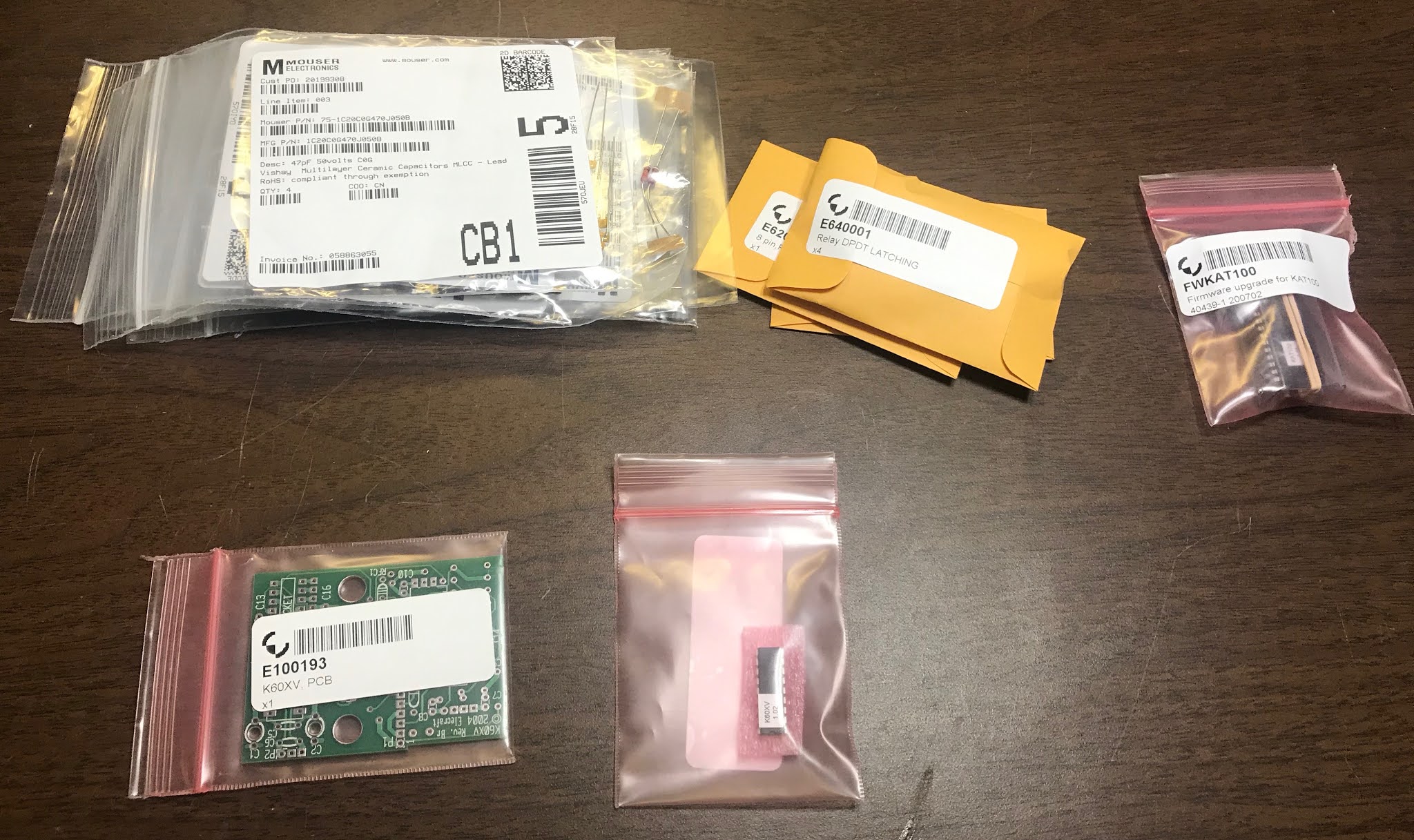
K60XV "Kit" - a collection of parts
I wrote to the Elecraft parts department, to check if certain parts were still available. I was delighted to find the K60XV PC Board and processed were still available in limited quantities. So, I put together an order:

  • E100193 - K60XV, PCB $24.93
  • E610018 - MCU, K60XV $6.60
  • E640001 - Relay DPDT LATCHING $2.60
  • E620005 - 8 pin FEMALE, 0.1LS $3.65
  • E620009 - 3 pin FEMALE, 0.1LS $2.08
  • E620076 - 8 pin MALE, 0.1LS, Elevated $2.49
  • E620077 - 3 pin MALE, 0.1LS, Elevated $0.92
  • E700090 - Nylon Stndff,3/16D,9/16L, Hex $1.18
These were all parts that were either exclusively from Elecraft, or those that I had trouble finding elsewhere.

I also ordered:
  • FWKAT100 - KAT100 F/W Upgrade to 1.05 $49.95
  • E700002 - TO220 Thermal Insulator, Adh $1.96
My KAT100 was older, and I needed the newer firmware for it to work on 60m. Installing the K60XV requires you to remove the heatsink panel, and I wanted to make sure I didn't destroy the thermal insulating pads.

For the rest of my parts, I combed through my junk box and also placed an order with Mouser. I didn't have any difficulty finding the rest of these parts. 

Board with parts in place.
The K60XV is not a complex option. If you've built the KSB2, this is piece of cake. The board goes together easily. I skipped installing C1 and C2. I had a couple of top adjusting 7-40 pF caps I planned to use. I waited to see what kind of clearance was available.

The main RF board requires a couple of modifications in order for the K60XV to function. This is probably the hardest part of installing this option.

If you were lucky enough to have a serial number of 3000 or higher, this job is much easier. For those of us with Rev A RF Boards, it's a little more difficult. 

D19 and D20 install.
The Rev A boards don't have a place for D19 or D20, so you have to mount them beneath the RF board. 

Hooking up the RF connection is a little picky as well. Take time when prepping the coaxial cable. Some folks have used heat shrink on both ends of the coax, but I didn't find that necessary.

I ended up being pretty happy with the RF board mods. 

RF line install finished.

These RF Board modifications require the heat sink panel to be removed. My early K2 (from 2002) didn't have the transverter holes on the heat sink panel, so I replaced it with the newer one. This requires the thermal insulating pads and the serial number sticker. I was actually a little nervous about this. I purchased spare pads, but I only had one shot at the sticker.

I shouldn't have been nervous. With a sharp knife, the sticker came off easily and transferred to the new panel with ease. The thermal insulating pads came off easily as well, and I had no trouble moving them.

I fitted the K60XV board and considered my options for installing C1 and C2. I considered installing my caps upside-down using short lengths of wire. However, there appeared to be plenty of clearance between the top of the K60XV board and the KPA100 shield. As I measured it, there was about 2mm of space between the top-mounted capacitors and the shield. So, I opted to mount them on top of the board. My caps were a perfect fit.

Rear view of the finished installation. Looks great.
Adjustment was easy. Set the D19 menu to Y, then adjust the C1 and C2 caps to peak 60m. 

Buttoning it all up again, I'm very pleased with the result. I don't know how long Elecraft's supply of parts will last, but if you really want a K60XV, you should inquire with Elecraft's parts department and see if they still have these parts available.

Monday, June 4, 2018

Cushcraft A50-3S

A50-3S standing ready.
A year ago I found a deal on a used Cushcraft A50-3S. I managed to scoop up this barely-used antenna for $80. It was missing the mast U-bolts, which set me back about $10 from Cushcraft. For less than $100, I had a functional 6m beam, which languished in my basement for way too many months.

I fixed that problem the past weekend. I got the 6m beam outside, put it on a mast and checked the SWR. My dimensions came out perfect, as the SWR curves were exactly where they were supposed to be.

The mast was something I had lying around. It originally supported a Butternut HF-4B beam and a long 17-element F9FT 2m beam. That was a long time ago - about 25 years.

The mast consists of two 10 foot sections of EMT. I would normally not recommend using EMT as a mast material. It's not a structural support, and the metal alloy is fairly ductile, as it is meant for bending. For really light-duty service, it can be adequate.

Sawhorses make for quick tune check
I don't remember the exact sizes of the tubes. I think the bottom tube is 1 1/2" EMT, and the top is 1 1/4" EMT. The top tube slides easily into the larger bottom tube. A 1/4" bolt about 12" from the top of the larger tube supports the smaller tube, giving an overall length just shy of 19 feet. An EMT coupler with some long bolts keeps the smaller tube firmly against the wall of the larger tube.

With the mast across the sawhorses, and the reflector just off the ground, the antenna is easily checked for tuning.

With that done, I just needed a way to hold the mast vertical. I already had an eight foot mast in the yard that used to hold the Cushcraft R7000. With a couple of short pieces of rope, the 19 foot mast was lashed to the eight foot mast. And, voila!

The lashings hold the mast firmly, but it can be rotated by hand. (aka Armstrong rotation) It may only be temporary for now, but it works quite well. I put many 6m stations in my log this weekend on FT8. It's good to have a real 6m antenna!

Monday, April 18, 2016

DXCC - Meeting the Challenge

Since I started uploading my logs to the ARRL Logbook of the World in November 2003, I've been working toward the DXCC Challenge. I've been carefully trying to work DX stations on multiple bands, hoping to get my current entity-band totals past the Challenge threshold of 1000.

Well, sometime this weekend, I received enough confirmations to get me past the 1000 mark. At the moment, I have 1003 entity-bands confirmed.

I guess I'll be submitting an application for the DXCC Challenge this year! That along with 30m DXCC.

UPDATE: I also notice that I have exactly 239 current entities confirmed for Mixed DXCC. This means I'm exactly 100 entities away from working all 339 current entities, or 91 away from the DXCC Honor Roll.


Saturday, February 2, 2013

Six Meters

In January, I operated the ARRL VHF Sweepstakes contest. I guess they don't call it that any more, it's just the January VHF contest. I haven't operated this contest since 1992, and have done no VHF events since 1993.

Back then, I had two Microwave Modules transverters: MMT144/28 and MMT220/28. I modified the latter with a new crystal to be based at 222 MHz. I had an F9FT long-boom yagi for 2m, and nothing more than crossed dipoles for 222 MHz. With 10 watts out, it wasn't much, but I made several dozen contacts on 2m. I never did make a contact on 222 MHz.

I sold that gear when I moved from Stone Mountain, GA. Instead, I focused mainly on operating HF, which is plenty challenging.

Upon receiving the K3/100 from my XYL for Christmas, I naturally had to give 6m a try. I've never before had 6m equipment. Well, that's not true. For a while, in the early 90s, I had a JR remote-control radio system on 6m that I used to fly model airplanes. But, you couldn't talk on that radio, so it doesn't really count, does it?

I had already worked four contacts on 6m on December 31st. I figured the 100 watts would be plenty to work quite a few contacts. While I don't have a 6m antenna, I could load up what I had with the tuner and make do.

On Saturday, I was also working the NAQP Phone contest, but occasionally I would take a minute and jump up to 6m and tune around for some activity. Nothing.

Sunday afternoon, I spent about four hours in the shack, mostly listening to static. I worked a few local stations, who could just barely hear me. I was beginning to wonder if I would work anyone outside my own grid.

Then it happened -- an opening. Just before 2300z, I worked K1TR in FN42. Fifteen minutes later, the opening started in earnest. I worked seven other stations up in the northeast in the next 45 minutes, along with about three locals. By HF contesting standards, it doesn't sound like much. But the signals from the northeast were booming in, and they didn't have any trouble hearing me, unlike the locals. The conditions moved like a spotlight down the eastern seaboard, ending somewhere in Virginia.

How exciting! I'm going to have to improvise a real antenna before the next VHF contest. Something with a bit of gain. Maybe a Moxon, or perhaps a three element beam. Maybe I can hide in up on the hill behind the Micro-shack. Rotating it would be nice as well.