Saturday, December 25, 2021

Fifty Years Ago - The AM Count-down

Original log book from
1971.
When I first got into radio, in 1971, I barely knew what I was doing. I had done some shortwave DXing with my GR-81, but that rig worked much better on the AM broadcast band than anywhere else. Just before labor day of 1971, I put up my first outdoor antenna. 

Previously, I had just used a spool of magnet wire strung around the ceiling of my attic bedroom. This was not a very good antenna. Just before school started in 1971, I bought a 25 foot roll of small speaker wire and unzipped it all. Soldering the two pieces together, this gave me 50 feet of antenna wire, which I strung out the window, across the garage and into a tree at the edge of the yard. 

I was eager to try this new antenna, so I proceeded to tune across the AM broadcast band that evening, and log each station I could. I started about 9 PM, and kept tuning until midnight. The next evening, I continued the process. 

Sep 3 log page.
That first night, I had started at the bottom of the band at worked my way upwards. The second evening, I continued upwards, but then reversed and went lower in frequency. This made more sense to me, and my later "countdowns" that I would make in subsequent years all started at the top of the broadcast band and continued toward the bottom. 

Sep 4 log page.
This event inspired me that for the next several years, I would try to do a "countdown" around Labor Day weekend. It marked the end of the summer, but also the beginning of the radio season. 

I remember it distinctly. I would sit patiently and wait for the AM stations to ID, generally at the top or bottom of the hour. If I got lucky, they would ID sooner. 

Hard to believe that event was over fifty years ago. 


Saturday, December 18, 2021

Oh, Wow, What a Year!

I can't believe I haven't posted in over six months. It's been an interesting year. Things really heated up quite a bit at work in the late spring, and I finally got the opportunity to take a couple of nice vacation times in the summer before Covid sprung back up.

And then, in October, when I finally thought I was hitting my stride at work a year after a position change -- they laid me off....

So, I've been busy looking for new employment. I'm happy to say that I have accepted a position that starts in January, so perhaps I can catch up on some much needed writing before then. 

Monday, May 3, 2021

Forty Years of Personal Computing - 6800 - The Need for Speed

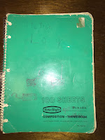
The 1.0 MHz clock board, attached to the back
of the MP-A CPU board.
When I ordered my SWPTc 6800 Computer System, I was expecting a 1 MHz 6800 computer. It wasn't quite.

Yes, 1 MHz seems glacially slow by today's standards, but this was 1977! And the Motorola and MOS Technology chips of that time could access memory in a single clock cycle, so they were just as fast as the Intel or Zilog chips at twice the clock speed. (Those devices needed two clock cycles, minimum, to access memory and typically ran 2-5 MHz)

Perhaps as a cost-saving measure, the SWTPc MP-A board only has one crystal. This crystal connects to the MC14411 bit rate generator, which requires one specific frequency: 1.8432 MHz. The MC14411 contains a number of divisor networks to offer common bit rates for serial communication. 

The designers of the MP-A used one of those outputs to drive the MC6800 at exactly 0.9216 MHz through clock conditioning circuitry. The MC6800 has two clock inputs that must be non-overlapping. This required about three integrated circuits and about 20 discrete components to produce. (Motorola later developed the MC6875 chip for this purpose. The later MC6802 had an on-chip clock oscillator and driver)

Clever, perhaps, but disappointing. It meant that my computer was almost 8% slower than specified. 

Harsh Reality

Original crystal from my MP-A.
All this assumes you are start with a 1.8432 MHz crystal. In my unit, the crystal was actually 1.7971 MHz! This must have been another cost-saving measure. Perhaps the 1.8432 crystals weren't available, or perhaps they were more costly, since they substituted a unit that was 2.5% slower. 

This meant that I didn't have a 0.921 MHz computer, I had a 0.89 MHz computer. It was 11% slower than 1 MHz.

This would not do. 

First Modification

Changing the clock speed is actually a simple matter - one need only introduce a clock signal into the conditioning circuits that drive the MC6800. All you needed was a crystal oscillator and a 1 MHz crystal.

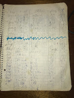
Close-up of the clock board.
I used a very simple circuit using two gates of a 7400 to create a very reliable oscillator. Even though this circuit was really simple, I wanted it to neatly attach to the CPU board. So, I etched a small circuit board. This was perhaps my second or third attempt at making a printed-circuit board, so it isn't pretty.

I masked the board by hand-painting etch resist. The lines are not very straight, and the lands have all different sizes. Most of the board was unetched and forms a ground plane that the crystal case is tied to. The result is very crude and rough.

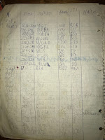
Crude but functional etching.
The smallest drill bit I had was quite large for the pins, so the chips and other components don't rest very snugly, and are held in with solder blobs. All of the parts came used out of my electronics junk box, so they are different sizes. Only three wires connect to the MP-A: 5 volt power, ground, and the oscillator output. 

It worked!

I now had a computer which was 11% faster than stock. At the time, It really felt like I had improved the computer.

Overclocking

Having an external clock oscillator means you can experiment with different clock speeds. Some time circa 1980, it dawned on me that I might push the processor faster than 1 MHz

Now, the Motorola 6800 microprocessor line had different codes for different speeds. No letter indicated 1 MHz, and "A" indicated 1.5 MHz, and "B" was 2 MHz (eg an MC68A00 is 1.5 MHz, and MC68B00 is 2 MHz). This wasn't just for the processor, but it applied to all the peripheral devices in the line (MC6810, MC6820, MC6830, MC6850, etc). All of my components were 1 MHz only. Could it possibly work at higher speeds?

At an electronics shop, I found a surplus 2.01 MHz crystal cheap, so I figured I'd give it a try. I removed the 1.0 MHz crystal and installed the new unit.

It worked!

I ran that computer for a couple of years in that configuration, and I never had a problem. Those 1 MHz components could work at 2 MHz, although likely not through the entire 0 to 70 degrees C rating for commercial devices. 

This experience proved useful several years later at work, circa 1985. We had upgraded from the 4.77 MHz IBM PCs to 6 MHz IBM ATs. Of course, I opened up mine immediately and noted that the CPU crystal was 12 MHz and socketed. A trip down to the electronic surplus store netted several crystals at 16, 18 and 20 MHz. That IBM AT on my desk would not boot up at 10 MHz (using the 20 MHz crystal), but it ran just fine at 9 MHz. I made the same modification to several other colleague's computers as well to 8 or 9 MHz. We ran that way for years. And when it came time to turn them in, the original 12 MHz crystal was easily swapped back in.

Wednesday, April 28, 2021

Remote Operation - Level 0 (RealVNC)

Sometimes experiment pays off. You never know until you try.

I was reading an article about remotely controlling computers over the internet. It occurred to me that if I could do this, it would be easy to operate FT8 from my Gwinnett QTH when I was at the Fulton QTH. Although I have rigs in both locations, Gwinnett is where I have the K3, and can operate on 6m. 

I started to research solutions. I found a product called RealVNC that can be licensed free for non-commercial use on up to five computers. Comes with a separate server and viewer product, and it works on Macs as well as Windows, Linux, even the Rasberry Pi. 

You have to create an account on their web site, but the installation was easy. I have a MacBook Pro hooked to the K3 at the Gwinnett QTH. I installed the server there. Then I installed the viewer software on a couple of Macs, and one Windows computer. 

Making the connection from Viewer to Server requires 2-factor authentication, so it is pretty secure. 

This software worked great. I was easily able to connect to the MacBook Pro and use WSJT-X. The K3 has to remain turned on, and I have no way to remotely change antennas, so I left it switched to the 3-element 6m beam. I also have no way to rotate the antenna remotely (it uses Armstrong rotation...), so I left the beam pointing SouthEast. I was hoping to pick up some propagation to the Caribbean or perhaps Central or South America. 

The first week of this experiment bore fruit the next day. I was in Fulton county, but checking I lucked into an opening to South America, where I worked two stations in Chile and two in Uruguay. Two new countries and four new grids! The next day, there was a powerful, but brief opening to the Cayman Islands, and Belize.

While one cannot predict 6m propagation, remote operating gives me a tool so I don't miss out on openings while I'm away from the Gwinnett QTH. 

This is only Level 0 of Remote Operating. I can only do FT8, and I can't change bands. That's next, I'm working on an automatic antenna switch driver to choose an antenna by the band selection of the K3. 

Wednesday, April 14, 2021

Forty Years of Personal Computing - SWTPc 6800

Old computer veteran from November 1977,
showing a few front-panel modifications.
After I completed the SWTPc CT-64, I ordered the SWTPc 6800 computer system in November of 1977. How much memory to order was a consideration. The original kit had the MP-M board with only 2 KB of memory. SWTPc changed this earlier that year to add an MP-MX expansion for a total of 4 KB. 

I wanted to run BASIC, plus the co-resident Assembler / Editor (called Co-Res), and this required 8 KB, plus space for programs. To basic kit, I added two MP-M boards. But, I did not order the MP-MX 2K expansion kits. I figured I could purchase the 2102 1Kx1 static RAM chips cheaper somewhere else. 

Design

The design of the SWTPc 6800 Computer System results from the MIKBUG ROM. Motorola developed MIKBUG to run a MC6800 evaluation kit. The essential features of the SWTPc system are drawn from this evaluation kit. The ROM resides at address E000, 128 bytes of RAM at A000, and a serial device at address 8004. 

The serial device is worth mentioning. For the original evaluation kit, the MC6850 serial device wasn't ready, so Motorola shipped the MC6820 parallel interface adapter (PIA), a bit of divider logic and used software to "bit-bang" all serial communications. SWTPc offered two serial port boards, the MP-C and the MP-S. The MP-C uses a MC6820, while the MP-S uses the MC6850 asynchronous communications interface adapter (ACIA). MIKBUG requires the PIA, so that's what the MP-C uses. This means that the original 6800 computer system cannot receive any characters from the console terminal unless the CPU is actively polling the MP-C I/O board.

The resulting memory map makes perfect sense for an evaluation kit, but left something to be desired as the system grew:
  • 0000-7FFF - available for RAM (32 KB)
  • 8000-9FFF - 32 bytes for the 8 I/O slots (4 bytes per slot) repeated
  • A000-BFFF - 128 bytes of ram repeated
  • C000-DFFF - available for RAM (8 KB)
  • E000-FFFF - 512 bytes of MIKBUG ROM repeated
Back in 1975, 32KB of memory space seemed enormous. SWTPc recommended only four 4K boards be installed, based on power supply considerations, which topped out at 16 KB. Later, it would become a serious constraint.

Building

The 6800 computer system kit consisted of several sub-kits:
  • MP-B Motherboard
  • MP-P Power Supply
  • MP-A CPU Board
  • MP-M + MP-MX 4K Memory Board
  • MP-C Console Serial Port Board
  • Metal chassis and case to house the computer
After my experience with the CT-64, I was prepared for SWTPc's minimalist assembly instructions.

MP-B Motherboard
MP-B

The MP-B was straightforward, although there are nearly 600 connections to solder the bus pins to the heavy bus traces. That was a lot to ask for my 25 watt Weller soldering pencil. The motherboard design has some decoding and buffering logic to separate the seven 50-pin main slots from the 30-pin I/O slots.

(In the picture, you'll note that I have replaced the original nylon spacers with #8 screws. SWTPc used nylon spacers that clipped into chassis bottom and allowed the MP-B to snap in. Those goofy nylon spacers never worked well and often would come loose from the chassis bottom. There's also some additional logic that enhances decoding -- more on that in a future article)

MP-P

I struggled a bit with the MP-P power supply. It had a lot of heavy wiring and board traces. But it is simple and went together quickly.

MP-A

MP-A CPU board
The heart of the whole computer system is the MP-A board. Compared to later CPU boards, there's quite a few discrete components on this board, related to the clock drivers and 555 reset timer. Given my experience with SWTPc kits, it wasn't difficult.

(You might notice my board is missing a few things - like the MC14411 chip and its associated crystal as well as the heatsink on the 7805. These components moved to other projects when the board was retired)

MP-M / MP-MX

MP-M 4KB memory
boards
The MP-M boards with the MP-MX expansion were the most dense. They have 32 total memory chips, plus seven other integrated circuits, two voltage regulators and a handful of discrete components, all on a 5 1/2" by 9" board. It was a lot of soldering. I did this twice, using parts from the second MP-M kit to act as the MP-MX kit. 

A few weeks later, I built the third MP-M/MP-MX, using 2102 chips I ordered by phone. It was cheaper, but not by a lot. There were a few other components for the MP-MX I either obtained from my junk box, or bought locally. You can tell that board by the yellow disc ceramic 0.01 uF capacitors. 

(In the photo, these boards are missing components, too. The molex connectors are missing from the center board, and the two top boards have donated their heatsinks as well. If you look closer, you'll find a few memory chips that are socketed or are mounted on socket pins. All these chips failed in the first couple of years of use and had to be replaced)

MP-C

MP-C board, modified
The MP-C was easy to build by comparison. Generally the I/O boards are really simple. The MP-C had nine integrated circuits, but three of these are six-pin opto-isolators. 

This board was designed to support RS-232 connections, as well as 20 mA current-loop interfaces that were typical of mechanical teletypewriters. 

(In the photo, the MP-C card has been modified into an MP-S type card using a MC6850 ACIA. The components related to the 20 mA current-loop interface have been removed, as well as the clock divider circuits)

Debugging

The big challenge for this kit was making it all work. Yes, I had a few solder-bridge problems with the CT-64 kit, but I managed to puzzle them out. It was easier where I could see things on the screen.

For the SWTPc 6800, this was harder. A lot of the system had to work to get the MIKBUG asterisk "*" prompt to show up. How as a kid who is not even 17 years old and owns no test equipment other than a cheap Volt-Ohm Meter going to do this?

I was lucky my father worked for a local college and they allowed me to borrow a dual-trace oscilloscope for a few weeks. This allowed me to track down my problems. I was experienced in building enough that I managed to avoid obvious problems like putting components in backwards, or putting the wrong components in a spot. 

You'll note most of the integrated circuits in the SWTPc kits are not socketed. Sockets were considered optional for most components. The MP-A board has sockets for four chips: MC6800, MC6810, MC6830 (MIKBUG), MC14411. The MP-C board has a socket for one chip: MC6820. There were no sockets supplied for the MP-B or MP-M/MX boards. Some builders opted to supply their own. 

Without sockets, it was important to place components correctly. Unsoldering misplaced components was not a pleasant experience, and it risked damage to the board.

That said, virtually every problem I encountered was either due to a solder bridge, or an unsoldered connection. The SWTPc boards had no solder mask (another cost-saving measure), so making accidental bridges was easy. I found solder bridges on the MP-A board, on the MP-B board, and several on the MP-M boards. 

Indeed, getting the memory boards to work correctly was enough of a challenge that it made me appreciate memory test programs. Some simple tests won't find memory convergence problems.

The SWTPc 6800 computer would function with only the MP-A and MP-C boards plugged in. The MIKBUG ROM monitor could be used to enter short machine language programs into the 128 bytes of scratch memory at A000.  This made it easy to test the other components, such as the MP-M boards.

The Unit

The resulting unit is a smart-looking turnkey box without any flashing lights. (Mine has been modified with 16 LEDs and a few other holes on the front panel, but I'll tell that story later) It came with aluminum angle trim, but I tended to leave it off. I generally had my hands in and out of the box so often I didn't even screw the lid on.

On the original kits, the back panel had four large holes which passed all I/O cables. In later units, SWTPc added punch-outs for DB-25 connectors for serial devices. Mine has four punch-outs arranged in two horizontal groups just inside the two outermost holes. Other units have four punch-outs in a line above the holes. Other builders have modified their back panels to add other connector types. 

Monday, March 8, 2021

Forty Years Of Personal Computing - SWTPc CT-64

CT-64 keyboard with switch options.
In the Fall of 1977, I was sixteen and a half years old. A classmate of mine had a 1970 Ford Torino that he was willing to sell for $1,500, and I had money saved from my paper route. While I didn't yet have my license, I considered purchasing this car. My father informed me that if I bought my own car, I'd be solely responsible for fuel, maintenance and insurance. After some deliberation, I made the wisest decision of my life -- I decided against the car, and instead spent my savings on computer equipment.

The Computer

After the mis-step with the Viatron 2111, I became selective. The KIM-1 experience was useful, but I wanted something more than a single-board computer. I wanted something that could grow into a larger machine without spending a fortune.

That meant a slot-based system, such as the S-100 bus computers. These devices cost in excess of $2000 once you bought all the components to do something useful -- beyond my budget. Plus, you needed a teletype or a terminal plus storage equipment. I needed something more affordable.

Southwest Technical Products Corporation (or SWTPc, as it was abbreviated) came out with the 6800 computer system in November 1975. I read all about the introduction in the October 1975 issue of 73 magazine. At $450, this machine was substantially cheaper than the S-100 computers of the day. It had no front panel, with the switches and LEDs, and the motherboard used far less expensive connectors. A 4K static memory board was $100, compared to an S-100 8K static memory board at $250. 

The Motorola MC6800 processor was no slouch. My older brother had spent some time at college programming a Tektronics 4051. It used the same processor, and seemed plenty capable.

The Terminal

By the time I was ready to spend money in the fall of 1977, I had decided on the SWTPc machine. But, where to start? It wouldn't do any good to buy the 6800 computer system first, because you needed a terminal to use it (no front panel, remember?). Therefore, my first order was the SWTPc CT-64 Terminal System.

Powered up after two
decades on the shelf
The CT-64 was a direct descendent of Don Lancaster's Television Typewriter. SWTPc had revised that design with their CT-1024 kit, which featured 16 lines of 32 upper-case only characters. (The CT-1024 was referred to as the TV Typewriter II) The CT-64 revised the design further with fewer boards and sported 16 lines of 64 characters, including upper and lower case. Displaying 64 characters per line required more video bandwidth than your typical television, so a composite video monitor is required. I had a small black and white TV that I though I could modify, so in October 1977, I ordered a kit.

Building

By 1977, I had built several electronic kits, starting with Heathkits, with their easy-to-follow instructions. The SWTPc kit was a new experience. The instructions were basically:
  • Insert all the resistors. Solder.
  • Insert all the capacitors. Solder.
  • Insert all the transistors and diodes. Solder.
  • ...
CT-64 main board.
You get the idea. The instructions were minimalist. The CT-64 the most difficult piece of equipment I'd ever assembled. The main board was very complicated with 47 integrated circuits, and covers most of the base of the CT-64. The memory board, serial board, keyboard and power supply were much easier to assemble. 

Nevertheless, I completed it the kit and got it working. I know I had a few difficulties like solder bridges to track down, but it worked as advertised and I was able to type characters and see them on the screen. That worked OK on my little black and white TV in 16x32 mode. 16x64 mode was illegible. I bought a 9" Sony black and white video monitor that worked perfectly.

I had one assembly problem -- the KBD-5 brackets are not mounted to the bottom chassis. If I put those screws in, I never could get the top case to go on. By leaving them out, the keyboard could "float" and find the most favorable position for the top case. 

In the first year of using the CT-64, I encountered two chip failures, something that has never happened with any other piece of equipment. The first chip to go was the AY5-2376 keyboard encoder. I ordered a replacement that has worked ever since.

Customization and Modification

The second failure happened gradually. IC22, the MCM6575L character-generator chip, slowly became flaky, and pixels of characters would flash on an off. Eventually, the chip failed entirely and every character became a solid block. I believe this was a thermal failure. 

Character set with MCM6571L
Finding chips is easier today, but in those days, I could not find a direct replacement. I did find an MCM6571L. This is a similar chip, with two important differences. The control character codes printed as greek characters, so it changed the control-character print function. The other difference was the row select lines were reversed. This meant the four row select lines had to be inverted before they made it into the MCM6571L. I added a small daughter board using an 74LS00 to invert these signals.

When I built my CT-64, I wanted to take advantage of every option. In addition to the standard UPPER / U + L and C.C. PNT switches, I added more switches:
  • Video memory PAGE 1 / AUTO / 2
  • RVSE - reverse characters - which sets the 8th bit
  • PAGE / SCROLL
  • Switch to the right of the POWER LED - No longer connected, I think this might have connected to DTR to allow one to stop scrolling. Honestly, I don't remember.
In retrospect, I never used the CT-64 in paged mode, so I could have dispensed with the PAGE 1 / AUTO / 2 and PAGE / SCROLL switches.
Legend for added
keycaps

The keyboard has other visible modifications. The KBD-5 lacks access to several characters. I modified the RCVE / XMIT switch so it was no longer locking, and that key sends the \ and | characters. The unmarked key in the lower right of the keyboard was wired to produce @ and `. (To modern users, it would seem impossible to use a keyboard that did not have an "@" key, but things were different in the mid-70s) The final character in the ASCII set is accessed by the ugly red pushbutton in the lower right corner. Pressing it gives an underscore _ and the DEL character. I painted the symbols beside each key.

My CT-64 was also set up with a number of control characters. Beyond the standard control characters of BEL, BS (cursor left), HT (cursor right), LF (cursor down), VT (cursor up) and CR (cursor to column 1), I wired in additional controls:

- Ctrl-F (ACK) toggles screen inversion - white and black or black on white
- Ctrl-L (FF) cursor to top of screen
- Ctrl-N (SO) toggle scrolling or page mode
- Ctrl-O (SI) clears the screen
- Ctrl-P (DLE) cursor to top of screen
- Ctrl-U (NAK) erase to end of line
- Ctrl-V (SYN) erase to end of screen
- Ctrl-Y (EM) toggles the cursor on or off
- Ctrl-\ (FS) toggle memory page

It's unusual that Ctrl-L and Ctrl-P perform the same function. I originally wired this function for Ctrl-L. However, the SWTBUG monitor has Clear Screen command that sends Ctrl-P followed by Ctrl-V. To be compatible, I added the additional wire.

While I was at Georgia Tech, this was enough control that I was able to create a profile for a full-screen editor for the CT-64 on the Software Tools Subsystem on the Pr1me minicomputers, and had fun editing at 300 baud via dial-up. I'm not sure why there are two different control characters for the home function.

Summary

CT-64 Insides
As terminals go, the CT-64 was limited. Terminals in that day were more typically 24 or 25 lines by 80 characters. The CT-64's 16 lines by 64 characters is a little more than half that space. Plus, it had a maximum speed of 1200 baud. Nonetheless, the CT-64 was a reasonable value in 1977. The kit sold for $325 when a typical terminal would cost $1000 or more. 

I used the CT-64 for several years, from 1977 until about 1985, when I bought a Wyse WY-85 -- a much more capable terminal. (24 or 25 lines by 80 or 132 columns, and 38,400 baud!)

The original Sony monitor from 1977 I used until 1983, when I loaned it to someone who took it to the People's Republic of China. It never came back. The gentleman who borrowed the Sony monitor bought a replacement Sanyo monitor. 

The CT-64 has sat on a shelf for a couple of decades until I recently pulled it out for this article. It mostly works -- the KBD-5 has some switch issues with the O, T and left Shift keys - they tend to stick in the up position. 

These days, computers don't even come with serial ports, much less require a terminal, so there's little demand for a slow, limited device such as the CT-64. It gave good service in the late 70s and early 80s.

Wednesday, January 20, 2021

Rebuilding the WARC Trap Inverted-V

Inverted V just below beam.

Fifteen years ago, I put up a trap Inverted-V antenna for 30/17m roughly the 12.5m level of the tower -- right above the rotator where the tower necks down to a single tube. A couple of years latter I added 12m traps to have  coverage of all the WARC bands. 

It was my first experiences building trap antennas. Naturally, I did everything wrong.

I originally created the traps using series-wound coax cable traps. They seemed easy enough to make, and pretty weather-proof. I also made the traps resonant in the band.

This article by Tom Rauch, W8JI showed me the error of my ways. 

Coaxial cable traps actually have a rather low Q. And any trap that is resonant in the band in use is going to induce more loss. Tom's advice is to make traps with discrete components, and put the trap resonance outside the band. 

Old coaxial Traps. The 17m traps are only 5
years old, but they are badly weathered.
From the modeling work I've done, a trap antenna works with the trap resonance just about anywhere between the two bands. I tend to push the resonant frequency close to, but just below the frequency - usually by 3-5%. They key is to make pairs of traps identical, so their resonant frequencies are  the same. 

I used a rather small value for the capacitor in the trap. The actual value isn't critical, anything will work. A smaller capacitor tends to couple less energy out past the trap above resonance. You'll always get some current in the entire antenna (unless you operate at trap resonance - but then you'll get the most trap loss, too). 

A smaller capacitor means a larger coil, and on the lower frequencies, this inductive loading shortens the antenna a bit. Pick a coil diameter so that the length / diameter ratio is somewhere between 1/2 and 1, as this generally results in higher Q. 

New traps, 17m on left, 12m on right.
The replacement traps are constructed on 1 1/2" schedule 20 PVC, which is roughly 1 5/8" OD as follows:
  • 12m - 6 turns 14 gauge THHN and a 22 pF 6 kV capacitor, resonating about 24.4 MHz
  • 17m - 9 turns 14 gauge THHN and a 27 pF 6 kV capacitor, resonating about 17 MHz
I used the existing length of 14 gauge THHN wire for the 12m segment, which, unfortunately, I did not measure. I'd start with 112" each side. the 17m segment is 18 1/2" of 12 gauge THHN each side, and the 30m segment is 93" 12 gauge THHN each side. The 30m segment is doubled back about 8" each side, twisted to connect to the end insulators. The total length of the antenna is about 37 feet.

I trimmed the Inverted-V by running it up the tower to about the 35 foot level using a rope and pulley. I learned this technique from the last time I repaired this antenna. This round, trimming only took four attempts. 

The antenna SWR curves fit perfectly on 30m and 12m, where the SWR is less than 1.5 and 1.2 across the entire band, respectively. 17m the SWR is closer to 2:1, with the lowest SWR at 18.010 at 1.58:1. In retrospect, perhaps I should have trimmed another 1/2" off the 17m segment. 

The apex of the Inverted-V is about 12.5 m high on the tower, about 8 feet below the A3S/A743. I used my RigExpert AA-55 to measure the SWR curves of the A3S/A743 before and after installing the WARC Inverted-V. There was no appreciable change in these curves on any band, which indicates there is little interaction between these antennas.