Showing posts with label Tribander. Show all posts

Sunday, February 23, 2025

The Challenge of a New QTH

A decade ago, my wife and I spent four years in Floyd County in one of her church postings. We loved the area, and imagined we'd retire there.

In November we took the first step. Bought a house in Floyd County near Rome, GA. House is on the top of a small mountain - Ward Mountain, rising 300 feet above the valley floor below. From the front porch, there is a gorgeous view to the West. On a clear day we can see 35 miles to Lavender Mountain, which is practically in Alabama,

The house is a little smaller than we'd like at 2100 square feet, but there's over 11 acres of land. A small office outbuilding with one room and a tiny bathroom has become the ham shack.

We've owned the house in Gwinnett county for 30 years. Now we are transferring things to the new house. There's a lot to do. We'll sell the Gwinnett house in the next months. In the meantime, I'm focused on building up the Floyd QTH when I have the energy.

Antennas are the first order of business. I first put up an 80/40/20m Trap Dipole. It's up about 12m in the trees. I erected a 160m Inverted-L with two elevated radials. It's a bit noisy, so receiving antennas are likely needed to make the most of that. I plan for three beverage antennas. A 6m dipole barely 4m up in the trees offers me an option on that band.

I've also put together the HF4B. I've mounted it on a 19 foot pole lashed to a deck post. It needs adjustment to work well. It's OK on 10m, but 15 and 20m aren't quite right.

I'm planning to put up a tower. I'll need to take down the tower in Gwinnett first. My plan is 70 feet of Rohn 25, with the A3S/A743 on top. 35 feet below that will be an A3S, pointed at Europe. This would give me a stack toward Europe, plus coverage in other directions with the top antenna. Horizon is unobstructed in every direction except to the NorthEast, where the two additional summits of the Ward Mountain chain are. Those peaks are just 100 feet and 140 feet higher, but they are 1 km and 2 km away, respectively.

I'm already seeing good results with the 80/40/20m trap dipole. There are benefits to being on the top of a mountain. Even a simple tower should be awesome.

For 6m, I'm on the lookout for a 5-6 element beam. The Cushcraft A50-3S i've been using in Gwinnett just doesn't have enough gain to work the intercontinental paths. 

On the office building, I've already moved in an operating desk with desktop shelves, and another luncheon table that serves as a workbench. The main part of the floor is a little more than nine feet square, And almost six feet of the rest of the building is split between the tiny bathroom and the rest of the floor. The desk and workbench are a bit of a squeeze.

A wire shelving rack takes up some of the space opposite the tiny bathroom, and gives me room to store things. I don't know how I'm going to get a whole basement of ham gear into this little building.

Such is the challenge of a new QTH.

Friday, October 21, 2022

The Single-Point Ground (SPG)

SPG all hooked up to coax
and control lines.
As radio amateurs, taking proper precautions against lightning and electrical surges can be a difficult and expensive proposition. We often neglect them and rely on luck.

After reading Bonding and Grounding for the Radio Amateur,  I decided it was worth the investment. I already had all ground connections - house, tower, station - bonded. What was missing was bonding the antenna connections to the ground as they entered the house. I needed a Single-Point Ground panel.

A Single-Point Ground is a metal panel or box providing a common bonding point for all cables as they enter a building. This metal is connected to the external ground rods, which are all bonded together. The idea is to bond the cables connected together, so that lightning or surge potentials all rise and fall together. Without a potential difference, damaging currents cannot flow. 

SPG panel ready to mount
on basement wall
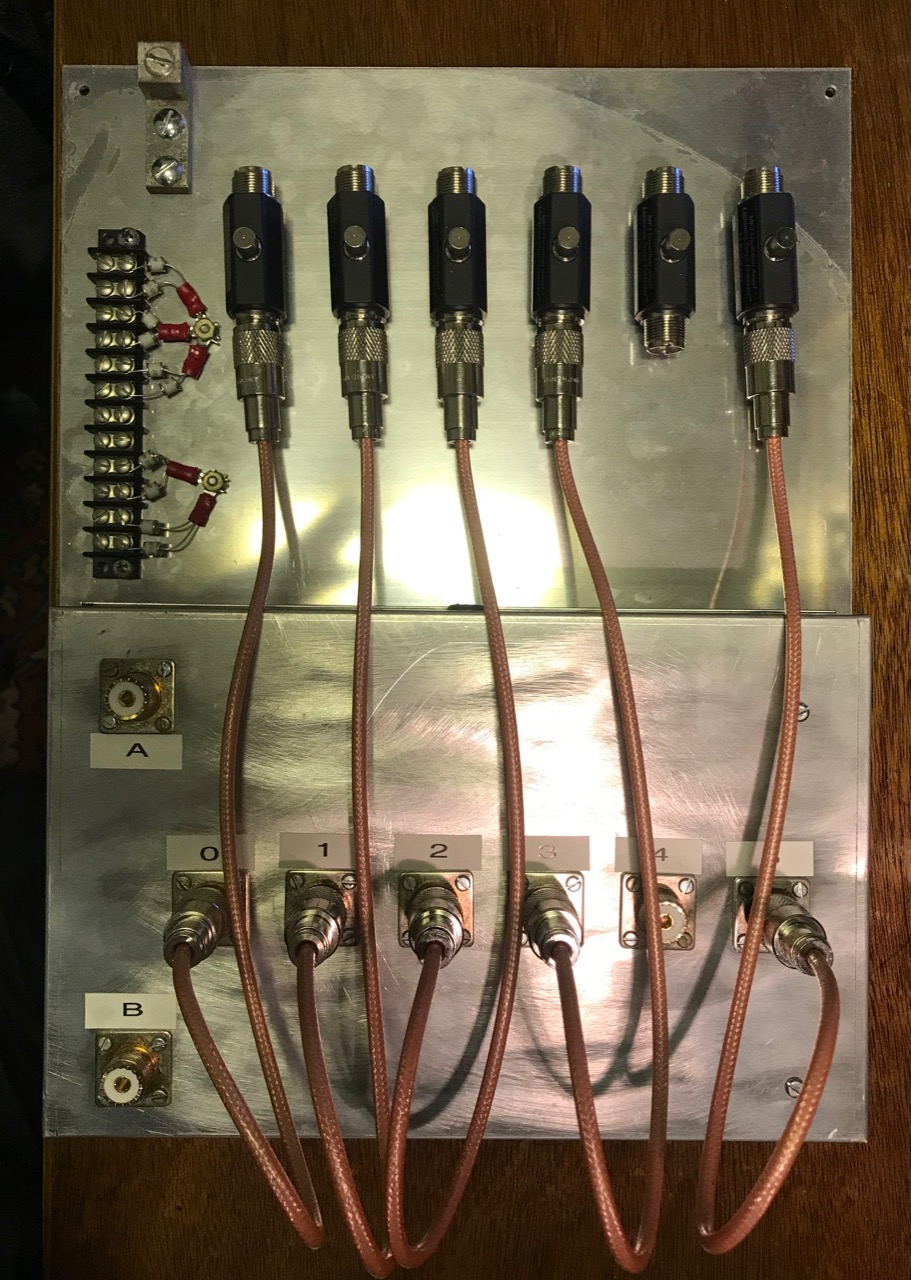
I cut a 0.090" Aluminum panel 12" by 16" and mounted the KK1L antenna switch to the bottom edge. I added lightning arrestors for the antenna coaxial cables, plus a barrier strip holding gas discharge tubes for the rotator and shunt antenna control cables.

I chose MFJ-272 lightning arrestors. I needed six of these, and the MFJ units were about $40 each. The Alpha Delta and Polyphaser units were more expensive. The arrestors are mounted to the panel with a single large screw, supplied with the arrestor.

Short coaxial jumpers connect the arresters to the KK1L switch. I made these out of 18 inches of RG-400 coax using new Amphenol UHF connectors and a UG-175 adapter. RG-400 is doubly-shielded, eliminating the potential for any coupling between the jumpers. (Notice I didn't quite have enough RG-400 for all six jumpers, so there are only five at the moment. I'll have to purchase more)

The panel mounts on the basement wall where the cables enter the house through a 4 inch PVC pipe. A grounding block connects a short piece of copper wire to an eight foot ground rod on the outside. The ground connection is also bonded to the perimeter ground wire between the house, tower and station grounds using a split bolt. 

I had a bit of trouble with the coax running from the A and B ports of the KK1L to the operating desk. Since the coax to the antennas ended at the basement wall, I trimmed some coax from the antenna feed lines. To get the right length, I pulled the feed lines outside, then trimmed them from the far end. Simple, eh? Except the first one looped around and got stuck, and the cut piece ended up being about five feet too short.

The next feed line was a newer run of Davis Buryflex. I ran it to the A3S/A743, and then cut the right length. For some reason, I had problems with the connectors on both ends, but once they were redone, the cable worked as expected. For a short while, I thought the cable itself might be defective.

To do these tests, I made good use of my RigExpert AA-55 Zoom. Which of two pieces of old coax is any good? The cable loss test is quick and give one real numbers to compare. You just need to test the coax both open and shorted. 

With the SPG installed, the next step is to automate the switching of the KK1L.

Monday, December 28, 2020

A3S/A743 Refurbished - Rotating Once Again

A3S/A743 QRV @ 15m
Since I took it down back in October, the A3S/A743 is once again proudly back at the top of my tower. It's been something of a long ordeal.

Refurbishing the antenna was delayed when I had to wait eight weeks to get traps out of MFJ -- they, like many companies have been greatly affected by the Coronavirus. Indeed, their biggest problem is getting parts from their suppliers, who are likewise affected.

Even after getting the parts, I had a lot of trouble tuning the A3S somewhere close to the bands. That required a lot of jockeying on the tower. It did give me a lot of time at the top of the tower, something that is always a confidence-builder.

I had a little trouble with the rotator yesterday -- one of the connector lugs came off the pigtail. This meant that while the rotator was in place, it wouldn't turn. I was tired from the long climb yesterday, and fixed it today. 

The good news is the antenna seems to be working correctly. I haven't worked a lot with it, but I'm sure I'll get a chance during the RTTY Roundup this next weekend. 

Hopefully, this antenna should serve me well for many years to come -- the initial installation worked for over fifteen years. Fifteen more would be fine by me.

Next project will be to fix the WARC trap dipole and put it back up.


Saturday, December 19, 2020

Tuning the A3S/A743

Adjusted A3S/A743, ready for rotator.
After adjusting the A3S/A743 on the ground and getting it back on the tower, I was very disappointed to find the SWR dips for each of 10, 15, 20 and 40m were all outside the band. They were all too low. This surprised me. When I measured the antenna with the beam facing upward, the dips were very close to the band. Now that the antenna was on the tower, it was going to be more difficult to adjust.

Rick Dougherty, NQ4I, gave me an important tip. Always measure horizontal antennas horizontally. Don't attempt to make measurements with the antenna vertical. With the antenna 6-8 feet off the ground, you can get a good sense of the measurements, knowing that the antenna will rise in frequency as it moves away from the ground. Generally by about 100-300 kHz at the 30 or 40 foot level. As you move further from the ground, the effect lessons. 

Rick knows his stuff -- he built a superstation in Griffin, GA, and has experienced this phenomena putting up dozens of antennas. 

OK, I didn't follow Rick's belated but sage advice - what should I do now? I didn't want to take the antenna off the tower again, it was a lot of trouble to get it up there in the first place. I decided I could make adjustments similar to how I added the A743 option originally - by tipping the Driven Element (DE) vertically and climbing down the tower.

On the tower adjusting
the now vertical DE.
One the first climb to make adjustments, I could already see part of the problem - some of the DE joints had slipped outward while the antenna was waiting to be installed pointed vertically. The extra weight of the A743 parts probably had something to do with this. 

Loosening the U-bolts for the DE and the support mast, the DE tipped over easily and I was able to climb down the tower and adjust. I had to make some of the adjustments somewhat blind, since I could not easily put a measuring tape against the elements. 

I ended up with the 10m traps out about 83.5" (A), the 10 and 15m traps spaced as 6" (B), and the 15 and 20m traps at 18.75" (C) -- this was the lower limit, since the tubing ends were contacting each other inside the support tube. the 40m portion I extended to about 66". These measurements are for each side of the DE.

This took two climbs, and ended up with the 10, 15 and 40m SWR curves well centered in the bands, and 20m right at the bottom of the band. This isn't perfect, but it is usable. Note I did not make any adjustments to the Reflector or Director, as they are well out of reach.

Next time I set up an A3S/A743, I think I will adjust the 10 and 15m portions to the MID-band settings, and split the MID and CW settings for 20 and 40m. That's roughly where I ended up anyway. 

I'll also consider replacing a lot of those stainless steel worm clamps. After being out in the weather for 30 years, a few of them would not tighten the way I would like. 

The A3S/A743 should be ready to go after one more climb to raise the antenna and install the rotator. I also plan to tweak the support mast a bit higher to keep water from accumulating in the 20m (TK) traps, since that's likely how they failed in the first place. 


Sunday, November 1, 2020

Rebuilding the A3S/A743

I've had the A3S/A743 down for several weeks now. I've gotten it mostly rebuilt, but I'm waiting on parts. More about that in a moment. 

I wrote previously about my inspection of the traps. The 20m TK traps are completely toast. But the TA (10m), TB and TC (15m) traps appeared to be fine. All the plastic end caps, however, were toast.

This particular A3S/A743 has been up for a while. I originally purchases the A3S in 1991. It spent three years in the air at the old Stone Mountain QTH, then several years in my basement in Gwinnett. Then it spend a couple of years on W1YM's tower while he was waiting for his Skyhawk to be delivered. And nineteen years at the Gwinnett QTH. All told, that's twenty-four years exposed to the elements. The A743 40m option has only been up fifteen years. 

A few years ago, I bought another A3S at a hamfest for $100. Such a deal! This unit was manufactured in 2007 and does not appear to have been outside for any length of time. The plastic end caps on the traps look practically new.

During the rebuild, I decided to use the TA, TB, and TC traps from Cushcraft #2 on the Cushcraft #1 tubing and vice versa. Cushcraft #2 isn't going up any time soon (perhaps when I move to another QTH and can build a 70 foot / 35 foot stack). I figured I would use the least weathered traps on the antenna that I'll be using. 

I used No-Al-Ox liberally when I assembled the A3S nearly twenty years ago. After nineteen years in the weather, much of the original application had evaporated, but the sections came apart easily after unclamping. The traps from Cushcraft #2 had never seen a drop of No-Al-Ox, unfortunately. So, as I intermixed the parts, I made sure I applied some to every joint. 

I ordered all new trap end caps, boom and element end caps from MFJ, along with new TK traps. Laird communications sold off Cushcraft several years ago to MFJ. I was happy that parts were still available. However, the ordering system left much to be desired. MFJ is in the middle of a web site re-design, and there's no way at present to order individual parts. Their older web site would list parts on the same page as the product, and you could click through to the parts link to order each one. Why they would switch to a new web site that doesn't have this capability is beyond me. 

A call MFJ with all the proper part numbers, I ordered everything pretty easily. Then it got weird. The gentleman on the phone didn't tell me the total of my order, he just guessed it would be $130-140, which is about what I expected. He estimated my order would ship in two weeks, and that I should see an order confirmation email and another email when the order shipped. All good, I thought.

Then I noticed my credit card was charged $169.90 almost immediately after I got off the phone. I waited a few days, but I received neither a order confirmation or shipping confirmation email.

This is not right. Indeed, this may be illegal. You're not supposed to charge someone for an order unless their goods have shipped. That's how it is supposed to work. I called and asked about it, and they said they corrected my email address and I should get a confirmation. My order hadn't shipped yet, because the TK traps needed to be manufactured, and that would take at least two weeks. Fine. But, then I didn't receive any order confirmation emails. A week after my original order, I called again, had my email address corrected again, and asked that a confirmation email be sent. This time, I received it. At that time, I was told my order would ship in ten days. 

And, sure enough, ten days later, they shipped something. I was surprised when I received a very small box -- clearly not large enough to contain the two TK traps. Opening it, I found my entire order of plastic end caps. But no traps. 

It's now been four weeks since I placed my order, and no indication they are shipping the traps that take them two weeks to manufacture. There have been at least two good weekends for putting the tribander back on the tower, but without traps, I can't finish the assembly.

Keep your fingers crossed I actually see these traps sometime soon.


Sunday, October 4, 2020

A3S/A743 On The Ground

A3S/A743 on the ground

I've known for some time now that my A3S/A743 has problems. Back in March 2019, I noticed that one of the 20m traps was arcing. Then a couple of months ago, I could see that several of the trap end caps were either missing or damaged. 

It's taken me several tower climbs to bring this antenna to the ground, but this weekend, we were finally able to successfully lower it down without incident.

My daughter Lauren acted as my ground crew and did an excellent job. I couldn't have done it without her.


Antenna mounted on tripod

Once the had the A3S/A743 on the ground, the next process was to carefully mark, measure and inspect the antenna. I didn't want the antenna lying on the ground. I had a roof tripod I'd picked up somewhere along the way, and with a short piece of mast, it allowed me to work on the antenna horizontal at ground level.

As soon as we had the antenna on the tripod, I marked all the traps. The original Cushcraft trap markings weather off rather easily. I used a sharpie to indicate the element, trap band, and an arrow pointing toward the boom. It will be important to reassemble the antenna with the traps in the correct direction.

DE traps showing disintegrating
end caps.

Next step was to mark all the element distances. This just required a quick sharpie mark at each tubing junction. 

After this, I got out a clipboard and a measuring tape, and took measurements of all element segment lengths for all three elements. I wanted to see how the antenna measurements matched up with my records. As it turns out, even after 19 years in the weather, the director and reflector elements were spot on. The driven element was a little asymmetric -- that likely happened when I added the A743 kit in 2005. 

DE support rope covered 
in lichen.

With the marking and measuring done, it was time to inspect the antenna. Overall, all of the aluminum tubing appears to be in fine shape -- nothing bent, warped or cracked. The traps were a concern. All of the trap end caps were either missing, damaged, cracked or weathered. Three of the element tips were missing, even the boom end caps bad broken. 

My daughter Lauren noticed the lichen growing on the antenna. Lichen covered a few trap end caps as well as the entire DE support rope.

I was surprised to find the bead balun in such good shape after 19 years. The feed line it surrounded seemed rather weathered, and it is my intention to replace it.

Next, I disassembled the antenna. Because I used No-Al-Ox 19 years ago, separating the sections was easy. Once a clamp was loose, they slid right off. I removed the traps and outer sections, leaving the center part of the elements intact. The outer sections I stored in my basement, and the traps went to the workbench. The boom and center part of the elements, I lashed to my back porch for now. 

With the outside work done, it was time to inspect the traps. I pulled all twenty-eight end caps off. Maybe four or five were intact, but even those are heavily weathered. I blew all traps out with compressed air, finding surprisingly little material come out, which I took as a good sign.

The two 20m (TK) traps were a concern. These traps I saw glowing back in March 2019. One of the end caps had melted. With the end caps off, I could see the outer end insulator on both traps had melted.

Only a little char on this one.
To know how bad it was, I had to disassemble the 20m traps. Disassembling these traps is a difficult proposition. The outer end of the trap cover is dented inward in four places to hold on to the end insulator. Because of this, it can only slide outward. The inner end of the trap cover has a double-z bend to make connection to the element tubing. If you undo the bend, the cover will slide off outward. But undoing the bend will likely break the aluminum. 

A lot of char on this one...

For the 20m traps, the outer insulators were toast anyway, so I didn't have any trouble sliding the trap cover inward. I just had to remove the screw at the double-z bend first. 

What I saw inside was not pretty. Both traps were damaged due to arcing and will need to be replaced. 

I also disassembled one of the 15m DE traps. Of course I broke the double-z bend in doing so. However, the inside of the trap looked clean, and, unlike the 20m trap, the coil windings were protected with resin. I didn't think it was worth disassembling any more traps and breaking more double-z bends.

I believe the 20m traps may have suffered from too much droop on the elements and collected a lot of moisture inside the trap. Once fired up with RF, it arced and toasted the traps. 

Some of the traps had corrosion evident around the hold-down screw on the trap covers. I removed the screw and put a thin layer of No-Al-Ox between the z-bend and the trap element tubing. This should limit further corrosion in this joint.


Sunday, August 2, 2020

OK, That's Not Good

Noticed today while I was mowing grass that two of the traps on the A3S/A743 -- the 15m trap on the director and the 20m trap on the driven element -- both have end caps that have come off the traps. 

This means the traps are exposed to the weather, insects and what not. 

That's not good. 

Indeed, from the ground, this antenna isn't operating correctly, either. The SWR is over 2 to 1 on 15 and 10m, and the antenna doesn't seem to be that effective on those bands, either. Only a little bit better on 20 and 40m.

The A3S has been up since 2001. I added the A743 in 2005. That's been 15 to 19 years exposed to the elements. It's not surprising this antenna needs maintenance.

I've got the gin pole on the tower, just need a couple of days at the Gwinnett QTH with a little help to get that antenna on the ground.

Sunday, August 25, 2019

Rebuilding the HF4B

It's been a long time since I picked up the Butternut HF4B project from a friend. I decided it would be a good fit at the Fulton County QTH. It's small enough to be supported by a mast, and will turn with a tiny rotator. I took all of the pieces to Fulton County, disassembled and cleaned everything, and took stock of what I needed.

The basic components seem to be OK. One of the 1/2" tubes is damaged with a gouge near the end, nearly ran over by a lawnmower no doubt, but will be serviceable. One of the 1 1/8" element support tubes has a crack. I've looked for a replacement locally without luck. I think for the moment I'll use a clamp to hold it together.

Two of the four doorknob capacitors have cracked. I managed to find five 75 pF caps at a hamfest a couple of years ago. I bought five in order to have a spare. These things are fragile.

All of the stainless hardware is serviceable despite being out in the weather for over 25 years. The U-bolts, however, are another story.

I don't know what genius thought it was a good idea to sell an antenna with zinc-plated U-bolts, lock washers and nuts. After 25 years of weather, they are rusted junk. Some of the legs broke off when trying to undo the nuts. Those that didn't are so rusty as to be unusable for any purpose.

I ordered replacement U-bolts from McMaster-Carr, who had exact replacements for a reasonable price. Except these are stainless steel.

With replacement hardware in hand, I started to re-assemble the antenna. The wires of the bowtie elements needed replacement. This antenna has eight of these, but only four survived to make it home with me. Of these, only one is intact. I used it to make measurements and make eight identical replacements.

I hit the a snag assembling the first element. The clamps that hold the vertical tubes aren't tight enough to keep them from rotating on the support tubes. Butternut replaced these sheet metal clamps with U-bolts in a later release, which would work better. This requires sleeving about four inches of the vertical tubes.

I guess that's what I'll have to do.

Tuesday, March 26, 2019

Uh Oh. Not Good.

Well, if it isn't one thing, it's another. After celebrating getting the A3S/A743 rotating again, I've found a problem. The SWR shifts I mentioned? On a dark night, I went outside and looked up at the antenna while WSJT-X was transmitting on FT8 trying to contact someone. I tried this on 40 and 20m.

I observed one of the 20m traps on the driven element light up with arcing using 100 watts. It was visible in the drain holes and end caps of the trap.

At the very least, I'll need to take the driven element down and rebuild it.

Update: I've tried this experiment on 15m, and I see no SWR shifts even using 500 watts. I think the problem may be confined to the 20m trap(s).

Monday, March 25, 2019

Rotating Again!

Well, it didn't take months after all. As I wrote last month, my A3S/A743 had been stationary since December. But with the beautiful spring weather here in Georgia, I managed to get to the top of the tower and finish the installation.

It's now rotating freely, as expected. It's really good to be able to use the beam as intended, and not have it fixed roughly east.

I do wonder if the A3S/A743 needs repair, however. I'm still seeing occasional SWR shifts at 100 watts on 40 and 20m. I'll need a gin pole to take the antenna down to refurbish.

Thursday, February 28, 2019

Back on the Tower Again

During my December vacation, I started a rather ambitious project on the tower. Since its installation, my A3S/A743 has been about eight inches from the very top of the mast. My intent was to put the beam at the very top of the mast, in order to give more room to stack an A50-3 under it.

It had been a while since I climbed on the tower, and any work at the very top is always nerve-wracking. As I've written before, sometimes you get up there and decide you've had enough.

Anyway, back to the December project. I conscripted my daughter Lauren to be my ground crew. I ascended the tower, removed the rotator and hung it from a couple of nylon loops off the side of the tower. Then I lowered the mast into the tower, until the A3S/A743 bracket was right at the top of the tower. The mast and antenna are somewhat heavy, weighing about 50 lbs. I relied on a pulley at the top and bottom of the tower and a haul rope to get support from my ground crew.

The tricky part of this operation was going to be moving the antenna higher on the mast. I had two options. First, I could loosen the bracket U-bolts, lift the antenna higher, then retighten. This would only take me about five hands, and I was only born with two. Second, I could loosen the bracket U-bolts, then lower the mast into the tower. While this seems easier, I had visions of the mast going too low and the antenna falling off the tower. Plus, I was afraid that we'd drop the mast and it would fall some 40-some feet into the base of the tower. And then the antenna would fall off the tower.

Plus, my daughter was having a lot of trouble getting sufficient leverage on my pull rope, which was 1/4". After being at the top of the tower a little over and hour, I decided to continue the project later.

Little did I know that it would take two months before I could get back up there!

In the intervening time, I had purchased 120 feet of 9/16" braided black poly rope. Our first order of business was to replace the existing 1/4" rope with this much more substantial lanyard. Once again with my trusty ground crew, we set out to complete the project.

With the bigger haul rope installed, I surveyed the top of the mast. I had thought that perhaps the antenna had slid down the mast in the 18 years it has been up. But a close examination of the mast showed no evidence of that. It had always been at that level.

Standing there 40-some odd feet in the air, 20 feet above the edge of my roof, I wondered if loosening the antenna would get me into a whole new world of problems. I decided at that moment I wasn't going to mount the A50-3 under the larger beam. What we needed to do was hoist the mast back and up and put the rotator back in place.

This proved to be a problem. Despite all her hauling away on the rope, Lauren was unable to raise the mast any significant distance. It was only with me grabbing the mast with two hands and pushing we were able to move it at all. I ended up locking down the mast with a couple of bolts in the tower and climbing down to solve the problem.

I had a ratcheting come-along, but hauling it up and using it on the tower was problematic. I ended up tying the come-along to a support pole, then hooking it into the haul rope via a tied loop. This would allow Lauren to use the come-along to provide lift, and I could manage things at the top of the tower.

After climbing back up, things moved a little more quickly. The come-along provided plenty of tension, but I found that I had to move the mast with my hands to get it to budge -- there's just too much friction and too much stretch in the poly rope. In a few minutes, we had the mast nearly back up into position. I had to re-position the pulley to get the last few inches to make room for the rotator.

With the mast locked down again, I hauled the rotator back into position. Thereupon I discovered two problems. First, one of the four nuts on the U-bolt that clamps the rotator to the mast was missing. In the two months on the tower, it apparently shook loose and fell off. Second, the rotator connection at the base of the rotator were loose -- one of the forked lugs had fallen off the wire and would need to be replaced.

Not having the necessary hardware at the top of the tower, I finished as much of the assembly as I could and came down the tower knowing that this project would be finished on another day. Hopefully, it won't take a couple of months to get back up there.


Wednesday, December 13, 2017

Brake Delay for Ham-M and Ham-II Control Boxes

A $30 hamfest find - CDE Ham-II rotator control box.
Proudly installed in the operating position.
When I put up my tower in 2001, I'd had read enough on the TowerTalk mailing list over the years to know about the importance of brake delay. This allows the rotating parts on the tower to coast to a complete stop before the brake wedge on the CDE rotator design engages. Without it, the rotator comes to a sudden and abrupt stop, causing a lot of torsional stress and making the antenna and tower elements wave around unnecessarily. That repeated stress could end up causing failures over time.

The original Ham-M design has no delay. Pushing the lever a little bit illuminates the meter and shows the position indication on the meter. A little more turns the rotator. The moment you stop pushing far enough to turn, the brake solenoid releases and engages on the rotator shell -- causing the sudden stop.

The original design schematic, sketched out in 2001.
Back in 2001, I came up with a very simple circuit. I had some Allied Controls 12 volt relays with a 1000 ohm coil. I figured I could rectify some of the AC from the motor terminals with a big enough capacitor to power the relay for a few seconds. I ended up drawing the circuit to the left.

50 volt PIV rectifiers might not be quite enough, so I wrote 100 v PIV on the design. I ended up using 1N4003 rectifiers which are 200 volt PIV.

I estimated 10 mA of current is necessary to keep the relay closed. Since the left and right motor connections are about 30 volts AC, rectified this would be about 42 volts. Putting a 2.2 K ohm resistor in series drops the voltage down to something less than 15 volts across the relay. All that remained was choosing the right sized capacitor. I had some 1000 uF low-profile capacitors in my junk box, so that was perfect, right? The RC value was around 3, so I expected a delay around  three to four seconds.

Imagine my shock when I actually built the thing and found it took something closer to fifteen seconds for the relay to open! Clearly, a lot less than the full 10 mA was necessary to hold the closed relay closed. I ended up modifying the circuit by placing a 1 K ohm resistor in parallel with the relay. This resulted in a delay closer to six seconds, which was just fine. The relay contacts are wired across the switch contacts for the solenoid, so the solenoid remains activated until the relay opens.
Relay board shoehorned in control box.

I built the circuit on a tiny piece of perfboard just a little bit bigger than the relay. Biggest problem was shoehorning it into the very crowded Ham-M control box.  I figured I could mount it on a right-angle bracket just behind the meter.

Wiring it into the circuit was harder. Assembled, the switch contacts of the Ham-M are inaccessible. I had to remove two sheet metal screws holding the meter panel to the base. That gave me access to the switch. After soldering up the leads, the meter panel goes back in place.

This circuit has been in use since 2001, and has worked great.

At a recent hamfest, I found a deal: a relatively pristine Ham-II control box for only $30. I bought it, brought it home and immediately determined it worked great. It would take the place of the Ham-M control box -- but it needed a brake delay.

The Ham-II design has three buttons. The center button supplies power to the brake solenoid and must be pressed for any power to reach the motor windings. Proper technique would have you press the center button and hold it, then engage the left or right button, holding until the antenna had moved to where you want it, releasing the left or right button, while continuing to hold the brake in with the center button.

Ham-II control box with brake delay installed.
However, if you just pop off the buttons, the brake wedge would slam into the rotator shell.... Not what we want.

It wasn't hard to find the same parts in the junk box. Another scrap of perfboard, a few minutes of soldering, and the same circuit was again created. Mounting in the Ham-II box is a much easier exercise, since there's plenty of empty space. Because four of the connections are to the switches, I elected to mount the board on the bottom of the box, just behind the switches. A threaded standoff was used on an existing screw to hold the board slightly above the switch contacts. The standoff also supplies the ground connection.

This circuit works great. In the Ham-M, the meter and lights would go off once the relay disengages. In the Ham-II, the meter and lights are on any time the box is turned on. It might be nice to have an indicator that the brake is engaged. Perhaps this will be a future addition.

Tuesday, February 28, 2017

The Station Notebook

When I originally set up my station as a novice, I didn't make a lot of notes. I wrote a few things on the back-side of my logbook pages: radios I used, antennas I put up. But, for the most part, I freely made changes to my setup without a lot of documentation.

Some years later, I had a small steno-style notebook lying around, and I used it to record certain information. Like the exact color-code of the RS-232 cables I wired up for my computer. That sort of thing was handy to have written down, because it saved a lot of reverse-engineering later I went to make another cable. But that was about it.

Perhaps a dozen years ago, I read a couple of articles about James Lawson, W2PV, and how he kept copious notebooks about his station. He even solved a sticky problem during a contest, because he kept notes about his antenna installation.

After that, I started writing more things down in my little Steno notebook. Most of it was changes I made to the station -- radios or antenna modifications. Or if something big happened -- like I blew up the amplifier. I recorded a lot more details, and I put dates on everything.

But when I began to spend most of my time out in Floyd County it put my little steno notebook out of reach. I had a new station and I still wanted to keep notes. My solution was dead simple -- I created a text document using TextEdit. I called it Floyd County Station Log.

Looking at it today, it's more like a diary. Each month, I put in a new heading: March 2017. And below that I record anything interesting that I do. I record the things that work, and I also record the things that don't work! If I don't do anything that month, I'll just change the heading to the next month.

The bottom of this document has a list of projects to be worked on. Silly now, since I'm no longer at that QTH: 6m antenna, K9AY controller, 20m and 30m traps for the dipole, tribander-Moxon  times 3 (now that's an interesting project I'll need to write about some day!), remote antenna switch, etc.

This method worked so well, in May 2015, I adopted it for my main station log. Not only did I make new entries, but I also entered all the data from the steno notebook. Plus, I went back through all of my contest comment submissions and recorded all the changes I had made to the station from November 1994 to date.

Today the Gwinnett County Station Log is a reasonably complete record of all the things I've done with the station for the last 22+ years. It has six pages of project notes at the end. Lots of stuff to work on! And, yes, I also have a smaller document for the Walton County Station Log.

I guess my point is that having a station notebook is extremely valuable. It doesn't matter if you use a small steno notebook, a spiral-bound notebook, a composition book with graph paper, a loose-leaf notebook, or a computer document. The important thing is to find a style that works for you to keep notes. After a while, there's just too much to try to remember. So keep good notes.


Saturday, January 9, 2016

Project From a Friend - HF4B

HF4B Parts, after sitting out in the weather
for about 25 years.
I had a friend call me the other day. She was licensed about 25 years ago as N4VMN, but her license has since lapsed. In any case, she had some antennas that had been sitting out at beside her house in Marietta for quite a few years now -- she wanted to know if I might know anyone who could make use of them.

Well, I'm always interested in antenna projects, and I could certainly use some smaller antennas, so I said, sure, I could use them.

She had a slightly bent Ringo Ranger, and an old Butternut HF4B. Ah, the Butternut HF4B. I had one in Stone Mountain, GA from late 1987 until 1991, when I replaced it with a Cushcraft A3S.

N4VMN lived in another part of the same subdivision back then. She gotten licensed, bought a rig, and put up this antenna on a roof tower -- and she did it all without consulting me. While I was a bit disappointed I couldn't have given her advice, I was still impressed that she managed to do it all herself.

My experience had been that the Cushcraft A3S worked way better than the HF4B, but the Butternut was a solid performer.

The HF4B is a light-weight, trap-less tribander that uses large bow-tie shaped elements and a clever matching network. It supports 10, 15 and 20m, also also works on 12m. I never could get mine to match well on 12m, but it worked OK on the other bands. Being only two elements, it didn't offer a lot of gain, but had solid front to back. On difficulty in dealing with this antenna was it was so three-dimensional, as the bow-tie supports go three feet above and below the elements. Overall, though, it is pretty small. It can be easily turned with a small TV-type rotator.

N4VMN's antenna had spent a couple of decades outside next to the house. I expected after all this time it might need some repairs. The U-bolts are all shot, and will need to be replaced. The bow-tie supports were all bent, but look repairable. All of the bow-tie wires were broken or missing. The matching network tube supports were all bent, but look repairable. One of the element tubes had filled with water at some point, froze, and split about five inches from the center insulator. It might be repaired with a clamp or two, but replacement is probably a better option. The two fiberglass insulators seem to be in OK shape, although they need to have some of the weathering sanded off and protected with a nice coat of flat black paint (as I did on the R7000).

OK, this is going to be a project, but it looks like what remains is serviceable. I could definitely use a small tribander at the Walton County QTH, or even as a South-America facing antenna in Gwinnett County. I'll have to work out a 20-25 foot support to mount it on, eventually.

Friday, June 12, 2015

Things I've Learned about Antennas - Horizontal Antennas

I've been fooling around with radio for more than 40 years. Finished my first receiver January 1971, so I guess it's closer to 44 years. In those early years, I didn't know anything about antennas. My initial antennas were nothing more than magnet wire strung up around my attic bedroom. They worked - Badly.

Over the years, I've learned a few bits of wisdom about antennas. This article is about:
  • Horizontal Antennas
Be they dipoles, center-fed Zepps, yagis, quads, Vee beams or rhombics -- horizontal antennas share one key characteristic -- their most important dimension is height above ground in wavelengths.

The height determines the radiation pattern, impedance and much of the loss. I remember a few years ago on the QRP mailing lists there was a hot debate about one of W4RNL's designs -- the "88 foot" dipole. When LB modeled this antenna -- meant to be a secondary or spare antenna when your beam failed in the middle of a contest -- he did so at 100 feet and also at 70 feet. 

This design was supposed to give reasonable performance on 80, 40 and 20m. 88 feet worked out to be about right. Long enough not to have too crazy impedance on 80m, and short enough to not have a lot of deep nulls on 20m. At 100 feet, I bet it is a pretty good performer. At 70 feet, it wasn't a slouch, either. The odd-ball impedance would make for some loss in the feed line, but for a spare antenna, that wasn't a huge concern.

From the discussions, you'd like that 88 feet was somehow a magic number that made everything work better. Heck, if you have the room make it a full-size 80m dipole then add a couple of traps, for pete's sake. And do you think those QRP stations put up that 88 feet of wire at 100 or even 70 feet? Heck no, they were down at more practical heights of 20-35 feet. 35 feet might be passible for 20m, since it is 1/2 wavelength up. But it is only 1/4 wavelength for 40m, and 1/8 wavelength for 80m. 

Here's the deal: the pattern of a dipole is hugely affected by the height above ground. About 1/2 wavelength, it just starts to have a bidirectional pattern, and only that at pretty high angles. Lower than 1/2 wavelength, it's basically got an ice-cream-cone shaped pattern going straight up. This pattern is rarely desirable.

How high is enough? At some point above about 2 wavelengths, the dipole pattern looks a lot more like free space. For beams, at these heights, you can start to get nulls in your pattern at useful angles, so you have to be careful. Somewhere between 1/2 and 2 wavelengths is generaly the "sweet" spot for horizontal antennas. For specific applications, your best bet is to model the antenna at the desired height and watch for undesirable nulls.

Given that most hams don't have supports for antennas above 50-70 feet, it's likely that any antenna below 20m is too low. Get those antennas as high as you can.

Saturday, April 28, 2012

Adding the A743 to the A3S

Unfortunately, I don't have any pictures to share of this, but Jerry NG6R's question this week reminded me of the ordeal -- so I figured I should share it with everyone. 


I added the A743 to the A3S in September of 2005. The A3S had been up on the tower for four years at this point. I remember running into some difficulty with this update.

  1. Remove Rotator - rather straightforward. Loosen the rotator clamps and lever the mast up a centimeter or two before tightening down the clamping screws on the tower top. Remove the rotator clamps, screws, unhook the rotator cables (you did use a weatherproof connector for this, didn't you?), and pull the rotator out. I think I attached a sling to the rotator and hung it off the side of the tower using a carabiner for the duration.
  2. Lower Mast and Antenna to Top of Tower - this step always makes me nervous, as I always think the 70+ lbs  of mast, antenna and whatnot is going to come crashing down suddenly and impale a foot, hand or arm as I loosen clamping screws in the tower top.
  3. Remove Driven Element. First loosen the U-bolt and swing the element up vertically. I then attached a sling just above the boom and then removed the U-bolt. (This way, the element can't get away from me an go crashing to the ground) Then attach to a rope and lower to the ground.
  4. Update Driven Element with A743 Components. Be sure to follow the tips in my original article. I used the dimensions half-way between CW and MID in the manual. Double-check your dimensions. Take care to avoid bending the capacity hat. Go ahead and attach the driven element support rope clamps, and tie the rope to one clamp. You can't tie the other side, since it has to go over the boom.
  5. Mount the Driven Element. This bit was tricky. The element is much harder to haul up the tower, since you have to avoid snagging the capacity hats. Bring it up vertically and attach the U-bolt, but don't tighten it down just yet. Toss the support rope over the boom and swing the driven element up so you can climb down and tie off the support rope. (Don't forget to put the support rope through the grommet on the support mast) Rotate the driven element back down to horizontal. The Driven Element is strong enough to support itself, at least in the short term.
  6. Mount the Driven Element Support Mast. Hardest bit. The amount of slack in the rope depends on where you put the support rope clamps and how long the rope is. I barely had enough slack to get the bottom U-bolt on the support mast. Once that is done you need to adjust the height of the mast to get the Driven Element level with the other elements. This is a tough operation, since you are above the tower, and have to hold the mast up with one hand and tighten the clamp with the other. Don't forget the twist in the rope. Without it, you'll be back up the tower in a year or two to replace the rope.
  7. Raise Mast and Antenna. Again a nervous operation. If your mast is heavy, you should use a come-along. Mine isn't terribly, so I used a pulley arrangement. 
  8. Replace Rotator. Reverse of the previous steps. 

Sounds simple, doesn't it? No. Well, it took me about a half-dozen climbs to finish this off in the fall of 2005, and then I had to do it again when the support rope broken. I haven't had any trouble since then.

Cushcraft A3S/A743 Performance

A3S/A743 pointed toward Europe.


Jerry, NG6R, e-mailed me this week in response to my posting on the Cushcraft A3S/A743. Jerry had sold his A3S to another ham who was wondering about getting the A743 add-on kit. He wanted me to share my experience with the antenna.


The specifications don't really change with the 40 or 30m add-on. This was true with my experience. I did the A743 update in-place, with the antenna still on the tower. (Something I'll share in another posting)


The performance on 20/15/10 was the same as before the update. On 40m, it is a dipole -- but a rotatable dipole. Beamwidth is pretty broad, about 100 degrees. There are noticeable nulls off the ends -- and some of that may depend on how high the antenna is mounted. Mine is at 15m (50 feet) high, which is still a little bit low for a 40m antenna.


If you can mount an inverted V or dipole significantly (8-15m) higher than the A3S, you might be better off with a wire antenna than the A743. At my QTH, the 15m high tower is the highest point in the lot, so the A3S/A743 is a great combination. 


In the picture, you can see the 80/40m trap dipole coming off horizontally to the left of the tower at the 12m level. This dipole is broadsize NE/SW. With only 3m difference in height, there's not a lot of difference in the two antennas, with the higher antenna having a slight edge on DX. During some domestic contests, I would rotate the A3S/A743 to point NE, giving me 360 degree coverage on 40m with a flick of the antenna switch.


(The 80/40m dipole has since moved to the micro-shack in Floyd County, GA)


Does it work? You bet. I have 40m WAS and 113 credits on LoTW for 40m, virtually all of them on this antenna. I'd prefer a two-element short 40m yagi, but my tower installation doesn't allow it. The A743 kit only adds a few pounds of weight and increases the turning radius by about a meter. It's a good addition to most A3S installations.

Thursday, July 16, 2009

Cushcraft A3S/A743

As mentioned before, I've been using a Cushcraft A3S for several years now. I purchased it back in 1989, had it up for about six years, in the basement for five, loaned out for a couple of years to W1YM, and then back up since 2001 at my QTH.

There's many things to admire about the A3S. It's quite rugged, having survived several freak Georgia ice storms, but it only weighs 25 lbs even with the 40m option. While it's one of the last tribanders designed without computer modelling, it has reasonable performance on a small boom of 14 feet. It's been a popular product both in home installtions and even for Field Day. I have one ham buddy who used to use one on a pneumatic mast mounted to his conversion van.

Here are some of the things that I have learned about the A3S and A743:
  • Tape the driven element insulator
A layer of electrical tape protects the driven element insulator from the Sun. There's not much of it exposed, but the sunlight will slowly break it down over time. Covered with tape, it will last forever. Use a sharp knife to open the U-bolt holes.
  • Tape the trap end caps
The plastic trap end caps won't last forever. After about 5-8 years in the Sun, they will split. Cushcraft also thinks quite a lot of them -- replacing all 24 end caps cost me almost $50 in 2000. Try to preserve them by placing a single layer of tape around the circumference of the cap where it goes over the trap tube. The flat ends don't tend to split, since they aren't under any tension.
  • Keep the trap holes down
While it is in the instruction manual, it's pretty easy to have an element section rotate and have one or more holes pointing anywhere but down. Leave them that way, and the traps will fill up with water quickly. Get the screw clamps on tight enough so the element sections don't rotate.
  • Mount traps the correct way
The traps are designed so that the end connected to the cover tube is closest to the boom. Make sure all of them are this way. If you are not sure which way they are, you can carefully slide an end cap off to check. Mark the trap tube with an arrow using a Sharpie so you can remember. If you put the trap on backwards, it may be hard to diagnose.
  • Use a balun
Cushcraft recommends making a balun by taking six loops of coax and taping them together. WA2SRQ wrote a posting to TowerTalk back in 1996 that showed that such a balun is much more effective when the turns are in a single layer and do not overlap or bunch. Six turns of coax on a 4 inch PVC form should work nicely. Ferrite beads a foot and a half long works well, too. I found a set of 10 of ferrite beads large enough to fit over RG-8 and wired them underneath the boom.
  • Twist the element support rope
With the A743 option, the driven element droops far too much, so Cushcraft includes a non-conductive support rope and support mast. The instructions show the support rope should have a twist right at the top of the support mast. The twist prevents the rope from sliding back and forth through the plastic grommet as the driven element moves in the wind. It will eventually break. Don't ask me how I know -- just remember to include the twist.
  • Element spacings
The A3S offers three choices of spacings along the elements, CW, MID and Phone. I took a tip from K7LXC. With the Cushcraft 40-2CD,
Steve recommends going half-way between the CW and MID settings.

The last time I had my A3S up, I used the Phone settings, and the SWR was very high at the bottom of the bands. So, I used values that were midway between CW and MID.

This results in a good compromise in covering the entire band. Here's the SWR curves through about 130 feet of RG-213.

Based on these graphs, I could probably shorten up the spacing between the 20m and 15m traps, and the 10m traps and the boom.

Regardless of the values you use, double check the measurements before putting the antenna up. When I first put up the A3S, the 10m director spacing was about six inches too short. You couldn' t tell from the SWR curves, but the antenna likely did not work as it should.

There may be better tribanders you can buy, but the Cushcraft A3S is a great performer. The A743 option adds 40m. At my QTH, this is my best 40m antenna, partly because it is mounted higher than anything else. Being able to rotate the pattern is often helpful in crowded contest conditions.


Tuesday, March 17, 2009

The Tribander Experience

Most hams start off on HF with modest antennas. Perhaps a simple wire dipole, or maybe a trap vertical. These simple antennas can work, and often work well -- when installed at the proper height and with the appropriate number of radials, respectively.

But those starting off often don't have the experience to do things quite right. My first ham antenna was a simple 40m inverted V -- it followed the roofline of the house on 6" standoffs. The apex was all of 25 feet up -- and the ends were only a couple of dozen inches from the ground. It worked, but not well. With the 50 or so watts I coaxed out of my novice rig, it did OK. I also tried various dipoles strung between trees and buildings, random wires, even a vertical made out of a slinky.

Anyone who uses these simple antennas often dreams of something better. I thought that the guys with the tribander at 50 feet had the high-end installations.

When I bought my own house, I wanted to put up some good antennas. First was a 300 foot longwire at about 15 feet high. Fed with an L-network, it could load up on all bands -- even 160m. It did not work well. For a while, I used a "Loop Skywire" -- a 80m full wavelength loop positioned horizontally. This was about 15 feet up -- just barely higher than the longwire. It worked OK, certainly better than the longwire. But really, none of these were any better than my novice antennas.

Somewhere along the line -- I had an epiphany: for horizontal antennas, the most important single dimension was the height above ground in wavelengths. I built an 80m dipole and got it up in the trees about 45 feet high. This antenna worked great -- much better than the Loop Skywire -- and it only required two supports instead of four.

I eventually put up a beam. First was a Butternut HF4B. It was mounted on a roof tower at a height of about 35 feet (10m). Certainly not optimal for a tribander. I eventually replaced the HF4B with a Cushcraft A3S. I've written about this antenna before -- it is probably one of the best of the small trapped tribanders.

When I moved to my current QTH, I decided not to repeat the roof tower experience. It took nearly seven years before I could save up enough to put up the tower. In the meantime, I used a number of dipoles at successively higher heights, a trapped vertical (the Cushcraft R7000), and even a couple of two-element delta-loop wire beams in the attic for 15 and 10m.

During this time, I had the fortune of being able to guest op at W4AN's superstation near Dahlonegah, GA. NQ4I also invited me to come and operate at his Multi-Multi station. These stations have multiple mono-banders for each band, often at heights much greater than your typical tribander-at-50-feet, and many times stacked mono-banders to certain areas. Operating at a super-station is pretty amazing.

Moving from a simple dipole or vertical to a tribander is an eye-opening experience. With a tribander, the band opens earlier, stays open longer, you have directivity that can bring stations out of the noise or null out unwanted signals. Bands you thought were dead come alive with signals. Pileups that were too big and crowded with a dipole are easily busted with the tribander.

It's curious that going from the tribander to monobanders or even stacked monobanders isn't as dramatic as the shift from a dipole to a tribander. Using a monobander or stacks is much like the tribander, only better. It isn't a sea-change.

Not every ham can afford towers and stacks, but every ham interested in HF ought to consider putting up a modest tower with a tribander. It will make a huge difference.