| The GE TDM-114 Data Set. The big toggle switch is my modification so I could turn it off. |
| Rear View of TDM-114. |
| Manual with unit. |
| Schematic |
Ramblings on Amateur Radio, Flying, Programming, Martial Arts, the Macintosh and Who Knows What.
| The GE TDM-114 Data Set. The big toggle switch is my modification so I could turn it off. |
| Rear View of TDM-114. |
| Manual with unit. |
| Schematic |
![]() |
| Yours truly, at the 1979 ISEF, with my exhibit. |
While writing the interpreter, my parents thought my efforts would make a good science fair project. I entered the West Virginia Area Fair. My father, being a professor there, was a judge. To avoid any conflict of interest, he did not judge my category.
My interpreter was by no means "done". I was still working on it. I put together an exhibit discussing the various things I did to improve computer performance, including fixing the CPU clock source.
I did well at the Area Fair, winning the US Air Force Honors award for the most outstanding exhibit in my category. I also placed first or second overall. This was a matter of debate. The first place winner would travel to the International Science and Engineering Fair (ISEF). This trip was sponsored, in part, by a consortium of coal mining operations. The other exhibitor I tied with had built an impressive and detailed model of a modern coal mining operation. The coal miners wanted to send him. After all, his exhibit said "COAL!"
The professors of science weren't that impressed with the model, and they wanted to send me. (My father, of course, declined to vote) They worked out a compromise. They would see how we did at the Regional Fair, and break the tie that way.
![]() |
| SPG all hooked up to coax and control lines. |
After reading Bonding and Grounding for the Radio Amateur, I decided it was worth the investment. I already had all ground connections - house, tower, station - bonded. What was missing was bonding the antenna connections to the ground as they entered the house. I needed a Single-Point Ground panel.
A Single-Point Ground is a metal panel or box providing a common bonding point for all cables as they enter a building. This metal is connected to the external ground rods, which are all bonded together. The idea is to bond the cables connected together, so that lightning or surge potentials all rise and fall together. Without a potential difference, damaging currents cannot flow.
![]() |
| SPG panel ready to mount on basement wall |
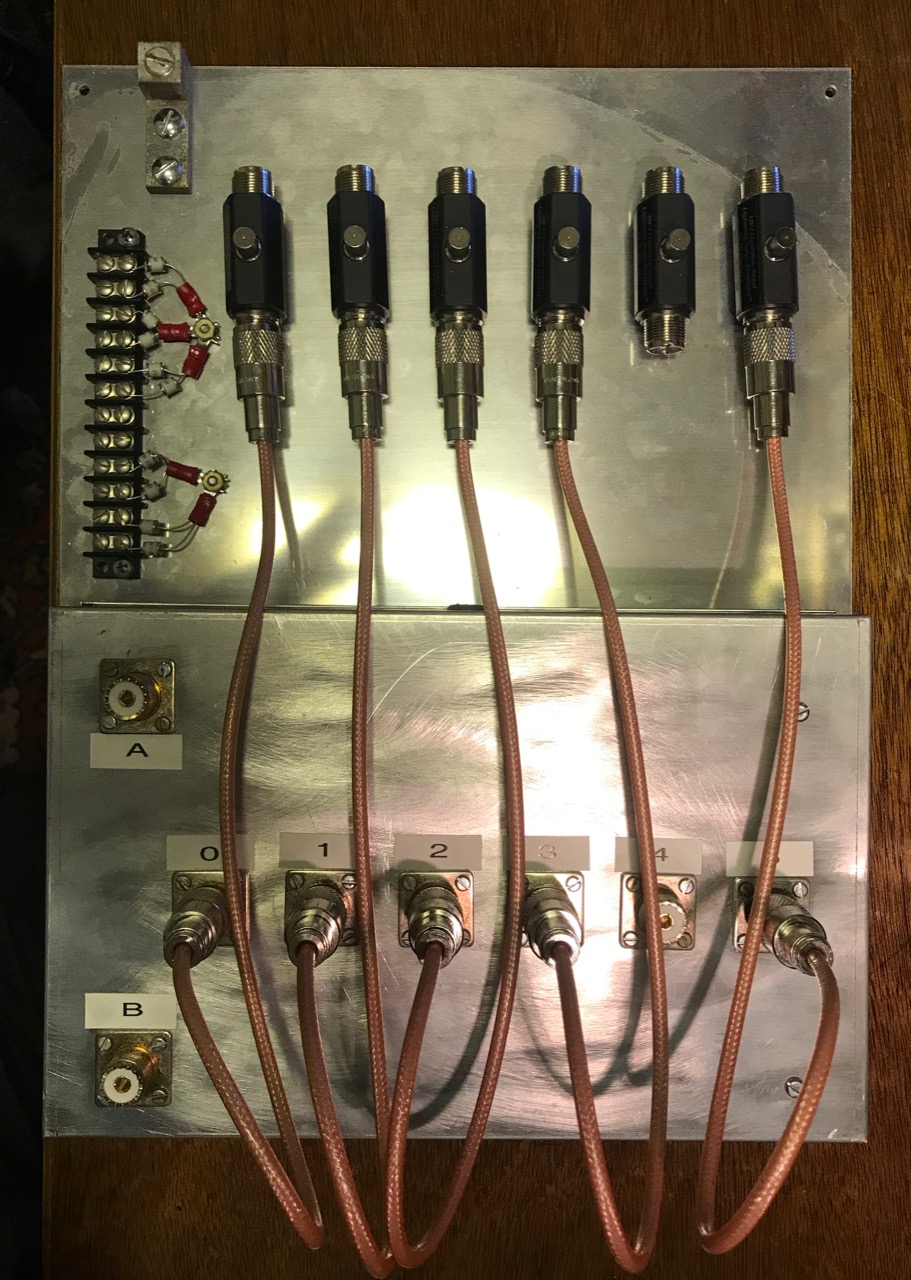
I chose MFJ-272 lightning arrestors. I needed six of these, and the MFJ units were about $40 each. The Alpha Delta and Polyphaser units were more expensive. The arrestors are mounted to the panel with a single large screw, supplied with the arrestor.
Short coaxial jumpers connect the arresters to the KK1L switch. I made these out of 18 inches of RG-400 coax using new Amphenol UHF connectors and a UG-175 adapter. RG-400 is doubly-shielded, eliminating the potential for any coupling between the jumpers. (Notice I didn't quite have enough RG-400 for all six jumpers, so there are only five at the moment. I'll have to purchase more)
The panel mounts on the basement wall where the cables enter the house through a 4 inch PVC pipe. A grounding block connects a short piece of copper wire to an eight foot ground rod on the outside. The ground connection is also bonded to the perimeter ground wire between the house, tower and station grounds using a split bolt.
I had a bit of trouble with the coax running from the A and B ports of the KK1L to the operating desk. Since the coax to the antennas ended at the basement wall, I trimmed some coax from the antenna feed lines. To get the right length, I pulled the feed lines outside, then trimmed them from the far end. Simple, eh? Except the first one looped around and got stuck, and the cut piece ended up being about five feet too short.
The next feed line was a newer run of Davis Buryflex. I ran it to the A3S/A743, and then cut the right length. For some reason, I had problems with the connectors on both ends, but once they were redone, the cable worked as expected. For a short while, I thought the cable itself might be defective.
To do these tests, I made good use of my RigExpert AA-55 Zoom. Which of two pieces of old coax is any good? The cable loss test is quick and give one real numbers to compare. You just need to test the coax both open and shorted.
With the SPG installed, the next step is to automate the switching of the KK1L.
![]() |
| Notebook containing the BASIC interpreter source code |
In the late 1970s, there weren't many computer languages available for small computer use. One either wrote BASIC or assembly language programs. Microsoft got their start this way -- selling BASIC interpreters to a variety of small computer manufacturers.
Assembly language is difficult. Having a high-level language, even one as, well, basic as BASIC made programming more accessible. I used Robert Uterwyk's 8K BASIC interpreter, sold as SWTPc 8K BASIC. When the Kilobaud articles came out, I was shocked to find the SWTPc 6800 Computer system ranked near the very bottom.
No way! The Motorola MC6800 was capable a spot near the top of the list, once you adjusted for relative clock speed -- a 2 MHz Z-80 or 8080 is equivalent to a 1 MHz 6800 or 6502. Something wasn't right. The problem wasn't the machine, it was the software.
My experience with SWTPc 8K BASIC showed there were three issues. First, it did no syntax checking on entry. This told me statements weren't parsed until the program was run. Second, each line had to be re-parsed during execution, which slowed things down further. The third wasn't really a bug. All the other BASIC interpreters used 32-bit floating point numbers for their calculations. SWTPc 8K BASIC floating point numbers used Binary Code Decimal (BCD), and supported nine-digits of precision and exponents of plus or minus 99. These numbers took six bytes to store, and many more instructions to calculate, but covered a larger numeric range and precision.
I decided I would write a BASIC interpreter. I started with math routines. My floating point format was straightforward. One byte was the exponent, and the next four bytes were the mantissa. Both were two's complement binary numbers. I worked on these routines hard, and manage to test them to the point I believed they were complete.
The math routines used a sixteen level expression stack, all in page zero. The bottom of the stack held the X and Y registers -- where all math operations took place. This meant the basic math operations where coded directly on X and Y using zero-page addressing modes -- which was very fast. In retrospect, this meant a lot of shuffling values around in memory. Given the MC6800's lack of registers, perhaps this was a reasonable choice.
Science Fair Project
At some point, this became a science fair project that got me to the International Science and Engineering Fair (ISEF) in San Antonio, TX. I'll tell that side of the story in a separate article.
The Interpreter
![]() |
| Flowchart of edit / command mode |
My editor parsed input on entry, storing keywords with one-byte tokens, where the high bit was set. This took less memory to store, plus it was faster to interpret. For this reason, I dubbed it a "compilative" interpreter -- due to the pre-parsed statements in memory.
I had decided my BASIC would replace SWTPc BASIC. It would support the same statements, functions and language. From the start, I allotted for every statement, function, and expression.
I continued to work on the interpreter in the spring, even as I was showing my exhibit at various science fairs. I was nowhere near done.
My style of working in those days was simple. I hand-wrote assembly language in notebooks, later typing it into the computer to build. Then I would write out the source and object to cassette tape. My terminal had only 16 lines, so hard copy in a notebook was easier to study. It also allowed me to write code when I wasn't at my computer -- like when I was at school.
The project grew a lot, and the source exceeded the capacity of my small system. There was more code than would fit in my 20 KB system with the co-resident assembler/editor loaded. I worked on it in sections.
![]() |
| "Compilative" Interpreter |
![]() |
| Cable management trays added to back of desktop selves. |
These systems can be expensive. I found a solution on Amazon.com that worked pretty well. It is a kit of eight cable raceway trays about 15" long, 1.5" wide and just under 1" tall. All for just about $20.
These worked well with my desktop shelves. Three cable trays fit neatly on the back of the shelves just under the copper pipe ground bus bar. I mounted them using three short wood screws on each tray.
The tops of the trays either slide or snap off. The fingers on the sides are easily displaced to insert wires of just about any size. In some cases, cables are routed in the trays from one end of the shelves to the other.
From the picture, there are still a lot of wires, but it is neater and more manageable than before. Many of those are antenna coax or power connections. The antenna coax will be moving to the back wall of the basement once the Single-Point Ground (SPG) panel is in place.
I also improved the bonding between units. I'm using 1/2" tinned copper braid, a fork lug and a cable clamp around the 1/2" copper tube grounding bus. This creates a low-impedance connection between the equipment and the station ground. In a few cases, I had to drill a hole and add some #6 screws and nuts to make the connection.
The best part is, I still have five left-over cable management trays to use elsewhere.
| MP-8M sans modifications. |
I ordered an 8KB memory board, the MP-8M. The board used 4Kx1 chips, compared to the 1Kx1 chips on the MP-M. Even though it held twice as much memory, the MP-8M looks barely populated by comparison. It also drew far less power. Notice the LM7805's have no heat sinks. The kit came with them, but they really aren't needed.
The original MP-M boards drew about 1.5 amps from the 8 volt supply for each board. SWTPc recommended running a maximum of four MP-M boards to avoid exceeding the capacity of the power supply. With the MP-8M, the machine could be populated to the 32 KB of continuous memory the MIKBUG memory map allowed.
At some point, I tried expanding the 8 KB board to 16 KB. I did this by buying 16 more 4Kx1 RAM chips and piggy-backing them on the original devices. All the pins were soldered except for the CE - Chip Enable (pin 10), which was raised to the side and wired together in two groups of eight. A couple of additional chips were used to drive the CE pin for the upper and lower 4 KB banks.
In theory, it should have worked. When the CE pin was high, the chips were unselected and all their outputs were in a tri-state mode. The decoder should select only one set of 8 chips at a time (or none at all, depending on the memory address).
I never could get it to work. The original 8KB worked fine, but the additional 8KB never responded properly. I suspect there was something incorrectly wired in my additional decoder. I removed the decoder circuits and left the piggyback chips. Eventually, I removed those as well.
One feature of the MP-8M was the write-protect switch. Flipping the switch made the memory unwritable. I never found a use for this feature, so I removed the switch.
Two other purchases I made in the summer of 1978 -- SWTBUG and the MP-LA. SWTBUG was a MIKBUG-compatable ROM with several extra features. Perhaps the most important feature was that it supported the MP-S serial interface, and not just the MP-C serial interface. More on this in a later article.
| MP-LA board. |
I cobbled together a small aluminum box that contained 8 red LEDs, plus a small audio amplifier. The amplifier design was taken from the May 1977 Kilobaud article, "Adding 'Plop' to Your System" (page 98).
| Kreepie Peepie - says so with dry-transfer letters. |
For some reason, I used two 7400 NAND gate chips. Probably because it was what I had one hand. This did not work the same, since the 7400 does not have open-collector outputs. But it worked despite my error.
The 8 LEDs connected to the B port of the MP-LA, and the audio amplifier was hooked to the CB2 control pin. The whole unit was powered by stealing 5 volts off the MP-LA's LM7805 regulator.
While it sounds simple, this tiny box was fascinating. I spent the next several weeks writing and modifying small assembly language programs to exercise it. Programming different patterns of the 8 LEDs was easy and fun. Animating the lights at different speeds required mastering delay loops in the code.| Inside the Kreepie Peepie. |
I spent a lot of time hand-modifying machine language programs and running them to see what new sound or LED pattern I could produce. One Saturday, my mother got really annoyed that I was playing with the computer instead of coming to dinner. She complained that I was spending "too much time with the kreepie peepie." And thus the little box was dubbed the Kreepie-Peepie. I even applied rub-on letters to the box with this name.
| Percom CIS-30+. Note that the handles of two switches have broken off. |
Around December 1977, I purchased the Percom CIS-30+ cassette tape interface. These interfaces allowed one to store and load programs on audio cassette tapes.
The CIS-30+ had major advantage over the SWTPc AC-30 cassette tape interface. Like the AC-30, the CIS-30+ supported the 300 bps Kansas City standard, but it could also record and decode at 600 and 1200 bps. This allowed programs to be stored and loaded two to four times faster.
| Insides of the CIS-30+. |
Originally, the CIS-30+ sat on top of the SWTPc 6800 Computer System. At some point, before I moved to Atlanta, I removed the board from the small aluminum case, and mounted it on the front panel of the SWTPc 6800 Computer System, in a space right above the power switches. This made the whole unit more compact, and reduced the number of cables that had to be dealt with.
I've since removed the cassette interface, and the holes that remain in the computer font panel.
The first program loaded was Rob Uterwick's Tiny Basic, which required 4 KB of memory. That was perfect for my machine, as it left 8 KB of space for programs.
Tiny Basic was distributed uniquely. The May 1977 issue of Interface Age contained a thin plastic record with Tiny Basic in Kansas City standard format. I jigged up a circuit so I could play the record on my family stereo and record it on a cassette tape. It took several tries to get the levels right, so the recording was readable. The magazine also had a hex dump of the program, so I verified that everything loaded correctly.
Tiny Basic was fun, but very limited - no string variables or functions. In the spring of 1978, I purchased SWTPc's 8K BASIC and the 6800 Co-Res Assembler / Editor.| Rob Uterwyk's 8K BASIC Manual. |
| 6800 Co-Res Manual. |
One of the magazines published a Fantasy Adventure text game in BASIC, and I managed to get it running on my computer. At school we had a "Fantasy and Renaissance Fair", and my computer was featured running this game as one of the exhibits.
Setting up the computer to run this game was an involved process. First, you had to load the BASIC interpreter. The first part of the 8K BASIC tape had a binary loader program (which was twice as fast as the Motorola S1 format). With that program loaded and executed, you would load BASIC. The second step, after BASIC was running, one loaded the game from a different cassette tape. Then one could execute the game. All of this was done at 1200 bps speed, and the process took nearly 30 minutes.
Someone managed to kick the power button on the computer in the middle of playing, turning it off. I spent the next 30 minutes of the festival re-starting the game....