Thursday, June 21, 2012

2Wire 2701HG-B Disconnect Problem - SOLVED

It's been eleven months since we got AT&T internet at the parsonage. At first, we ordered Comcast internet. They even sent us a modem. But there was this little problem of not actually having a cable plant out in the country where the parsonage is. They did finally quote us a price -- $5400 to install cable. No thanks.

So, we were thankful to get 6 Mbps/.5 Mbps AT&T DSL. They installed the 2Wire 2701HG-B Modem/Router/Wireless access point. This has been OK, except for one nagging problem.

Randomly, without warning, the router INTERNET indicator would go dark, the DSL indicator would go red and start blinking. Soon, the DSL indicator would turn to green blinking, then solid green, and the INTERNET indicator came back green. This takes 8-10 seconds, all the time the internet would be inaccessible. This might happen a couple of times a day, but more like twenty -- and more often, it seemed when someone was actively trying to use the internet.

This was especially bad when I was using Skype or my cell phone (my microcell is connected through the same internet connection). Or if I was using a virtual private network connection (VPN) to my work computers. That disruption would reset the VPN connection, and I'd have to go through a ten step process to reconnect. Perhaps two minutes later, I could try to work again. At least until it tries to reset.

Last weekend, I finally got tired of it. So I searched the web for information. Using some of the diagnostic pages inside the 2Wire router, I determined that the sequence of flashing lights represented a DSL Link Retrain. Those of you old enough to use analog modems will remember the distinctive sound of tones just before the modem connected. A DSL Link Retrain is much the same think -- only at 300 kHz instead of at audio frequencies.

Further searching revealed several articles by those unimpressed with 2wire products. One of the options is simply to replace the router. Being a ham, I'm not one to want to rush out and spend money I don't have to.

The AT&T Community Support forum unearthed an excellent thread: AT&T 2Wire 2701HG-B Disconnects / Drops. This had six pages of comments, and it took nearly an hour to read.

One of the suggestions was to measure the throughput of the connection using SpeedTest.Net, in order to determine that the DSL line was provisioned correctly by the phone company. When I tried this, as soon as I hit the uplink test -- DSL Link Retrain. I tried it a half-dozen more times. Every time I hit the uplink test, the router would do a DSL Link Retrain, save one. I now had a reproducible test, so I could try the various suggestions.

  1. Turn Packet Flood Attack Detection to Off - the theory is that activity on the router looks like a denial of service attack. Easy enough. Turn off the settings and try again. DSL Link Retrain.
  2. Move the Power Supply Brick to the Wall Outlet - theory here is that the 2Wire devices have marginal power supplies, and any reduction in voltage might cause a random glitch when the device draws power when doing something. Another easy test - replug and try again. DSL Link Retrain.
  3. Switch to 802.11b Wireless Networking - the theory here is that the 2wire devices can't internally handle the speed of 802.11g (54 Mbps) and the slower 802.11b (11 Mbps) allows the device to work correctly. Change the settings, re-do the wireless connection on the computer and try again. No DSL Link Retrain in five tries. 
At this point, I switched back to 802.11g, just to be sure the problem didn't just randomly go away. DSL Link Retrain. OK -- I'm not real happy about running 802.11b all the time. Not because of the internet connection, because it is only 6 Mbps/.5 Mbps anyway. No, two things bother me. First, I have other devices on the wireless network, such as iPads and iPhones, and I don't relish synching them at 11 Mbps. Second, the results from SpeedTest.NET were about 10% slower on 802.11b than on 802.11g.

I did notice that the router does have a speed limit setting for 802.11g. I switched it to a limit of 12 Mbps and tried again. No DSL Link Retrain in five tries. OK -- that works. And my 10% improvement in internet speed over 802.11b is back. Good. Try limit of 24 Mbps. DSL Link Retrain. The only other setting between them is 18 Mbps so try again. No DSL Link Retrain.

I've been running like this for most of a week and am pleased to say that I have suffered no further DSL Link Retrains logged by the router. It seems that high wireless speeds cause the router to reset the DSL connection. 

Frankly, this seems to be a product defect. It might be best to disable the wireless access point in the device and instead use a separate wireless access point connected to one of the Ethernet ports. (Unless, of course, that triggers the problem) I have not tested this.

A better solution may be to replace the 2Wire equipment with something that actually works. If anyone has suggestions, let me know. In the meantime, I'll be enjoying my slower (but working) wireless internet.

Saturday, May 19, 2012

Rebuilding the Ancient Mini-MOS Keyer

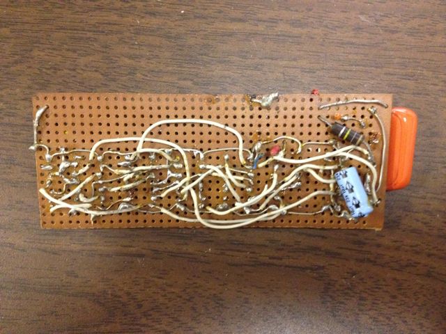
My 30+ year old Mini-MOS keyer, still going strong.
Back in 1979, before Volunteer Examiners, FCC testing sessions were hard to find outside of major cities. My Novice license had lapsed, so I took the opportunity at the Jackson's Mill, WV hamfest and sat for the General class exam. Much to the surprise of the examiners, I passed and was soon in possession of N8BHE.

One problem with this callsign on a straight key was the succession of dits. Getting all those dits out in the suffix would wear out my arm. Although I tried a bit of SSB operation on my Heathkit SB-301/401 combo, my primary mode of operation was CW, and it took a while before I ventured much outside the familiar confines of the Novice bands. Since my code speed was already up to about 15 wpm, it was time to upgrade to a keyer.

I ordered a Ham-Key HK-1 set of paddles, but I figured I could build a keyer. I remembered an article in 73 Magazine about a CMOS keyer, and there was even a followup with some improvements. The Mini-MOS keyer was still pretty new technology in 1979. Finding the CMOS parts turned out to be a challenge. My local parts stores didn't have all the exact parts, particularly the CMOS gates. However, they did have 74C equivalents.

Since I didn't need the sidetone generator (my rig already had that), and the character-spacing completion circuit seemed overkill at the time, I re-designed the circuit to use the parts I could find. I did use the dual D-type flip-flop input for the paddles to keep the paddle common at chassis ground. I ended up using two 4013, two 74C02, two 74C08 an a 4020.

The original 3-D wiring of the Mini-MOS.
Oddly enough, I don't have a schematic for this keyer. I never drew one. Somehow, I did the re-design on the fly. The original keyer was constructed with a bit of 0.1-inch perfboard, solder-tail sockets and some 22 gauge wire. I did draw a wiring diagram that I still have. (More on this in a moment) It's amazing this thing worked at all -- those tiny bare wires so close to each other, kept from shorting out only by careful bending into a three-dimensional structure.

This keyer worked great. I used it with the Heathkit SB-301/401 combo, later with a borrowed Yaesu FT-101EE, and even with a DX-60B. When I bought the Kenwood TS-430S in 1985, it was the first rig without grid-block keying, so I had to remove the keying transistor and key it directly from the CMOS gates. The CMOS chips lived up to the low power consumption -- the battery lasts for basically it's shelf-life. Over 30 years, I've probably replaced that battery eight or nine times.

I even built one of these keyers for my brother Ben, NJ8J. For his unit, I used wire-wrap construction, rather than go through the 3-D wire sculpture routine again.

This keyer worked great until last fall, when I couldn't get it to work. After a bit of troubleshooting, I concluded that the 3-D wiring had finally given up the ghost, so I decided to rebuild it using wire-wrap construction.

The old board just floated in the metal box. The new
board is held in place with two screws and spacers.
The keyer I made for my brother Ben was my first exposure to wire-wrap, but certainly not my last. In 1983 I designed and built (with the help of a classmate) a new 6809 CPU board for an old Southwest Technical Products (SWTPc) 6800 computer. I've also designed and built a couple of floppy disk controllers and other boards using this type of construction. (And that's probably plenty of material for another article)

I actually prefer a 3M product that uses IDC (insulation-displacement connections) over wire-wrap, but, unfortunately, this product wasn't that popular with 3M, and I don't know if you can buy it any more.

Having plenty of wire-wrap sockets and tools, I pulled out the 30+ year old wiring diagram and re-created the circuitry. This process did not take more than about an hour. Plug the chips in, connect the battery, and ... it doesn't work.

By now I was beginning to doubt of the 30+ year old chips were still functioning, that somehow a stray static charge had blown out one of the gates. A bit of troubleshooting shows that the master oscillator isn't oscillating. Maybe the 74C02's are bad? I put them into a protoboard and checked them out. Heh, even with no connections, the gates are oscillating at around 2 MHz. (This is why you always need to tie unused inputs to ground or Vdd). A bit of work with a few resistors and an LED proves the 74C02 works just fine. OK, why won't it oscillate?

Debugging this was slow work, and I wasn't making progress -- which is why I eventually ordered the K1EL K12 Keyer board. But even after finishing the K12 Keyer, I still wanted to know what was wrong with the Mini-MOS.

Several weeks later, I finally got the oscillator to go. However, the speeds were all wrong. Trying to adjust the speed range I found the oscillator would quit. A bit more work I discovered the underlying cause: my 30+ year old wiring diagram had an error in it. Yes, one of the resistors was shown connecting to the wrong junction. When the resistance got below a certain point, there wasn't enough hysteresis to trigger the oscillator and it would quit. Easily fixed by moving one wire. Oh, and, of course, I corrected the wiring diagram.

The keyer works again like it always did. I hope it lasts another 30 years. I want to try it out with the 40m Novice Transmitter.


Sunday, May 6, 2012

GQP 2012 - Floyd County

The operating position from Floyd County. The ancient
Toshiba logged the Qs, the MacBook monitored
spotting networks.
I managed to put in a pretty good effort for the Georgia QSO Party from the microshack. Managed a total of nearly 14 out of the 20 possible hours operating. 


Much of this was calling CQ. I was pleasantly surprised to find I could keep up a decent rate most of the time. I probably could have scored a bit higher had I not tried so hard to make Qs on every band. 


The station, as you can see is not elaborate. Venerable TS-430S with an AT-250 antenna tuner. Used the R7000 from 40-10m, and the 80/40m dipole for 80 and 40m. The dipole is pretty low -- only 3m high -- so it is a real worm -burner.


The TS-430S does not have the QRM-fighting power of the Elecraft K2. There were a number of times someone moved in close to my running frequency and I had to slide away, because I could hear. 


Running on CW was very effective on both 20 and 40m. Oddly, though, I could never get anything going on 20m phone. 40m was the big-time money band, with over 2/3 of the contacts taking place ont hat band. I started off using the R7000 on 40m, but I found the worm-burner dipole to be much more effective overall. It really needs to go higher. I can't wait to see how well it will work way up in the trees.


Many thanks to the folks who spotted me. I could tell a few times when it happened with a flurry of callers. 


I did have one odd incident on Sunday around 2210z. I had been running near 7042 kHz for nearly a half hour, when suddenly I was blasted with a high-speed, run-together CW that started off OKNOMORE.... and was laced with profanity. I knew I had a problem when I moved up half a kHZ and he followed me a minute later. I switched to phone for 10 minutes then came back to CW in a different part of the band. I hope this lid did not bother anyone else. 


This is my best GQP score ever, with more phone Qs alone than my Phone-only efforts.

Summary:
Band  CW-Dig Qs  Ph Qs
------------------------
 160:      0        0
  80:     53       11
  40:    215      232
  20:    115        4
  15:     16        5
  10:      0        0
   6:      0        0
------------------------
Total:    399      252  

CW-Dig Mults = 44  
Ph Mults = 32  
Total Score = 79,648

Club: South East Contest Club


Saturday, April 28, 2012

Adding the A743 to the A3S

Unfortunately, I don't have any pictures to share of this, but Jerry NG6R's question this week reminded me of the ordeal -- so I figured I should share it with everyone. 


I added the A743 to the A3S in September of 2005. The A3S had been up on the tower for four years at this point. I remember running into some difficulty with this update.

  1. Remove Rotator - rather straightforward. Loosen the rotator clamps and lever the mast up a centimeter or two before tightening down the clamping screws on the tower top. Remove the rotator clamps, screws, unhook the rotator cables (you did use a weatherproof connector for this, didn't you?), and pull the rotator out. I think I attached a sling to the rotator and hung it off the side of the tower using a carabiner for the duration.
  2. Lower Mast and Antenna to Top of Tower - this step always makes me nervous, as I always think the 70+ lbs  of mast, antenna and whatnot is going to come crashing down suddenly and impale a foot, hand or arm as I loosen clamping screws in the tower top.
  3. Remove Driven Element. First loosen the U-bolt and swing the element up vertically. I then attached a sling just above the boom and then removed the U-bolt. (This way, the element can't get away from me an go crashing to the ground) Then attach to a rope and lower to the ground.
  4. Update Driven Element with A743 Components. Be sure to follow the tips in my original article. I used the dimensions half-way between CW and MID in the manual. Double-check your dimensions. Take care to avoid bending the capacity hat. Go ahead and attach the driven element support rope clamps, and tie the rope to one clamp. You can't tie the other side, since it has to go over the boom.
  5. Mount the Driven Element. This bit was tricky. The element is much harder to haul up the tower, since you have to avoid snagging the capacity hats. Bring it up vertically and attach the U-bolt, but don't tighten it down just yet. Toss the support rope over the boom and swing the driven element up so you can climb down and tie off the support rope. (Don't forget to put the support rope through the grommet on the support mast) Rotate the driven element back down to horizontal. The Driven Element is strong enough to support itself, at least in the short term.
  6. Mount the Driven Element Support Mast. Hardest bit. The amount of slack in the rope depends on where you put the support rope clamps and how long the rope is. I barely had enough slack to get the bottom U-bolt on the support mast. Once that is done you need to adjust the height of the mast to get the Driven Element level with the other elements. This is a tough operation, since you are above the tower, and have to hold the mast up with one hand and tighten the clamp with the other. Don't forget the twist in the rope. Without it, you'll be back up the tower in a year or two to replace the rope.
  7. Raise Mast and Antenna. Again a nervous operation. If your mast is heavy, you should use a come-along. Mine isn't terribly, so I used a pulley arrangement. 
  8. Replace Rotator. Reverse of the previous steps. 

Sounds simple, doesn't it? No. Well, it took me about a half-dozen climbs to finish this off in the fall of 2005, and then I had to do it again when the support rope broken. I haven't had any trouble since then.

Cushcraft A3S/A743 Performance

A3S/A743 pointed toward Europe.


Jerry, NG6R, e-mailed me this week in response to my posting on the Cushcraft A3S/A743. Jerry had sold his A3S to another ham who was wondering about getting the A743 add-on kit. He wanted me to share my experience with the antenna.


The specifications don't really change with the 40 or 30m add-on. This was true with my experience. I did the A743 update in-place, with the antenna still on the tower. (Something I'll share in another posting)


The performance on 20/15/10 was the same as before the update. On 40m, it is a dipole -- but a rotatable dipole. Beamwidth is pretty broad, about 100 degrees. There are noticeable nulls off the ends -- and some of that may depend on how high the antenna is mounted. Mine is at 15m (50 feet) high, which is still a little bit low for a 40m antenna.


If you can mount an inverted V or dipole significantly (8-15m) higher than the A3S, you might be better off with a wire antenna than the A743. At my QTH, the 15m high tower is the highest point in the lot, so the A3S/A743 is a great combination. 


In the picture, you can see the 80/40m trap dipole coming off horizontally to the left of the tower at the 12m level. This dipole is broadsize NE/SW. With only 3m difference in height, there's not a lot of difference in the two antennas, with the higher antenna having a slight edge on DX. During some domestic contests, I would rotate the A3S/A743 to point NE, giving me 360 degree coverage on 40m with a flick of the antenna switch.


(The 80/40m dipole has since moved to the micro-shack in Floyd County, GA)


Does it work? You bet. I have 40m WAS and 113 credits on LoTW for 40m, virtually all of them on this antenna. I'd prefer a two-element short 40m yagi, but my tower installation doesn't allow it. The A743 kit only adds a few pounds of weight and increases the turning radius by about a meter. It's a good addition to most A3S installations.

Thursday, April 5, 2012

K1EL K12 Keyer

Finished K1EL Keyer with Ancient HamKey
HK-1 Iambic paddles.
My 30+ year old CMOS Keyer gave up the ghost -- the point-to-point wiring apparently was suffering from a failure. I tried re-building it using wire-wrap, but the troubleshooting was taking too long. I figured I needed to quickly build a replacement keyer that I can use right now with my TS430S.

I remembered that Curtiss used to make a keyer chip. But a quick search found that the original Curtiss devices were no longer available, although MFJ purchased the rights and offers a slightly updated chip.

Honestly, at the time I looked at this, the chip was $45, which seemed way more than I wanted to spend on a "temporary" keyer. A bit more searching brought me to K1EL's web page.

K12-BAT kit, as it comes from K1EL.
K1EL offers a number of interesting devices and components. The WinKeyer I had heard of -- but frankly, the name put me off slightly, as I've been a long-time Macintosh fan. Imagine my surprise to discover there's nothing "Windows" about the WinKeyer. It looks like a superior product for providing CW keying facilities in a contest station.

But that would be a project for another day. Today, I just needed a simple keyer. And I found it. The K1EL K12 keyer chip filled the bill nicely, and had 6 programmable memories and a host of other features to boot. All for less than $10!

Even better, there was a kit -- only $17. I quickly ordered the K12-BAT and within the week had the package pictured above.

There's not even two dozen components.
There's not a whole lot to the kit -- printed circuit board, socket and chip, transistor, battery holder, and a handful of resistors and capacitors. This would not be a bad first kit for someone. For me, it took less than 30 minutes to assemble.

Finished circuit board.
Once assembled, I wired up the paddles and tried it out. The command structure takes a bit of getting used to -- it's hard to remember for some of the longer commands what comes when.

However, it is quite a serviceable keyer. But, I can't just have wires strewn all over the bench. (Well, actually, I can, but that's not how I like to operate) Digging through my junk box I found a used cast aluminum box that might make a decent cabinet. The hard question was -- what to use for the seven pushbutton switches I needed? Nothing I had in the junk box was small enough to fit in the aluminum box.

Wiring was easy.
The upcoming Dalton hamfest provided the answer. If found some surplus switches that were small enough to fit, and they were cheap, so I bought eight. A subminiature potentiometer filled out the required parts list.

Drilling out the enclosure took a more time than building the board. But the wiring was very straightforward.

All done but the hard part.
At this point, I had a functional keyer in a rather ugly enclosure. Finishing the enclosure took more effort. Removing the board switches and pot left me with an empty enclosure. You can see that it had some kind of adhesive on the top, as well as a bit of corrosion here and there.

The best treatment, I've found, for stout aluminum like this is wire brushing. The oxide and other compounds come off easily, and the steel bristles of the wire wheel score the aluminum just enough to give it a nice texture. Best not to do it in a hurry and don't use too much pressure. I did both and ended up with some deep scratches in the top and a wire-brushed left index finger.

Of course, I had to wire brush it again. I painted the enclosure with the same flat black paint I used to repair the R7000. The end result is pretty sweet.

I'm still trying to figure out how to use the K1EL K12 keyer. In trying to program one of the memories, I have found it is very, very sensitive to character timing. I probably need to read the manual again. In any case, I am very happy with the K1EL K12 Keyer kit. I would highly recommend it to anyone who needs a sophisticated, yet inexpensive keyer.


Saturday, February 25, 2012

Straight Key Night 2012

Novice transmitter, receiver, and the venerable TS-430S with
the AT-250 auto antenna tuner round out the operating bench.
Yes! Straight Key Night. 2012 makes the sixth year in row I have operated this event. Once again putting  the "Novice" Transmitter on the air, paired with the very capable superhet receiver.

This year, I didn't have any technical problems with either the transmitter or receiver. In fact, they worked pretty much flawlessly (other than the fact that I was missing the stereo to mono adapter for the receiver and had to copy everything with one ear). The interesting thing this year is where they were.

Of course, I had set this equipment up in the Micro-Shack. While not much more than a storage closet, it actually does have just enough room to set up and operate a modest amount of radio.

With a little bit of help from a space heater, it was actually quite cozy during the January 1st operating event. Not much in the antenna department. I believe I favored the low 80/40m dipole rather than the R7000.

As I've written before, being crystal controlled means you have to call CQ. After making a couple of contacts, I decided it would be fun to make at least one contact with every crystal in my arsenal. My ten crystals span the 40m band from 7001.25 to 7121.1 kHz. Some of the frequencies are quite popular, whereas others are pretty far away from heart of SKN activity. Oddly enough, it was the popular frequencies that were the hardest to complete -- they were almost always in use.

I was successful in not only making at least one contact on 7001.25, 7006.7, 7010, 7038, 7042, 7047, 7050, 7061.1, 7075, and 7121.1 kHz, but also making one contact on 10108 kHz. I had just gotten two crystals for 30m this past Christmas, and they tuned right up in the "Novice" transmitter. Of course, the little receiver couldn't be used, so I used the TS430S for that role.

Fifteen total contacts, to twelve different states: VA, MI, FL, GA, TN, TX, PA, MN, IN, AL, NY, NC. My best ever SKN outing.